ZLX-ESP32-2
ESP32-C5 2,8 "Touch-Display-Entwicklungsboard
1. Produktübersicht
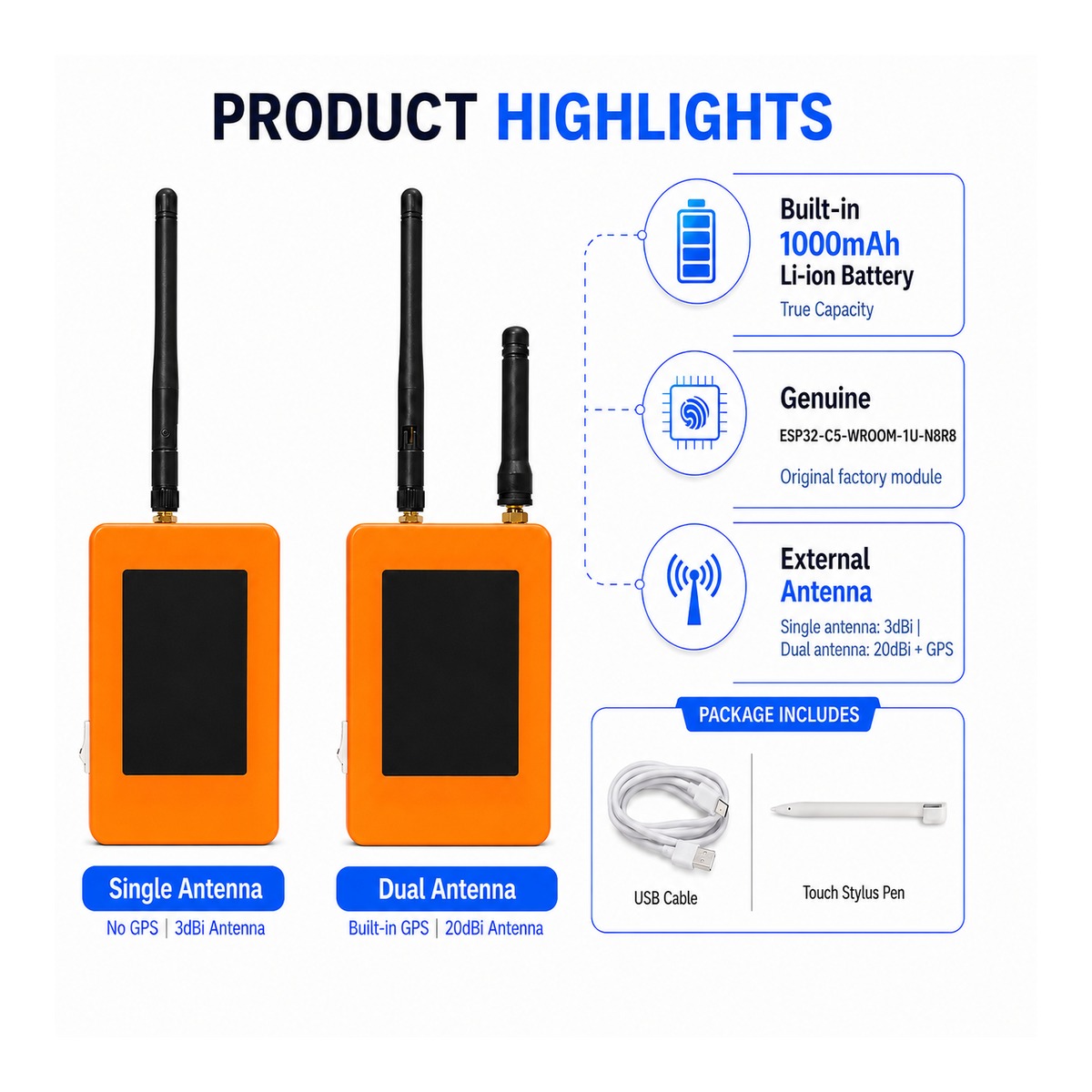
Das ZLX-ESP32-2 ist ein 2,8-Zoll-Widerstands-Touch-Entwicklungsboard, das auf dem ESP32-C5-WROOM-1U-N8R8-Modul basiert. Es integriert ein Farb-LCD-Display, einen XPT2046-Touch-Controller, einen microSD/TF-Kartensteckplatz (nur Kartensteckplatz, ausgenommen microSD/TF-Karte), eine GPS-Schnittstelle, einen Audioausgang, eine Batteriespannungserkennung, eine grüne LED-Anzeige, eine Start-/Reset-Taste und eine externe Antennenschnittstelle. Es eignet sich für die Entwicklung von Wi-Fi 6, Bluetooth LE, Zigbee/Thread, Mensch-Maschine-Schnittstelle (HMI), Datenprotokollierung und Internet der Dinge (IoT).
Merkmal :
- ESP32-C5 32-Bit RISC-V Single Core CPU @ 240 MHz
- ESP32-C5-WROOM-1U-N8R8: 8 MB Flash + 8 MB PSRAM (Onboard-Modulspeicher, Nicht-MicroSD/TF-Karte)
- 2,4 GHz + 5 GHz Dualband Wi-Fi 6 (802.11ax)
- Bluetooth LE、IEEE 802.15.4、Zigbee 3.0、Thread 1.4
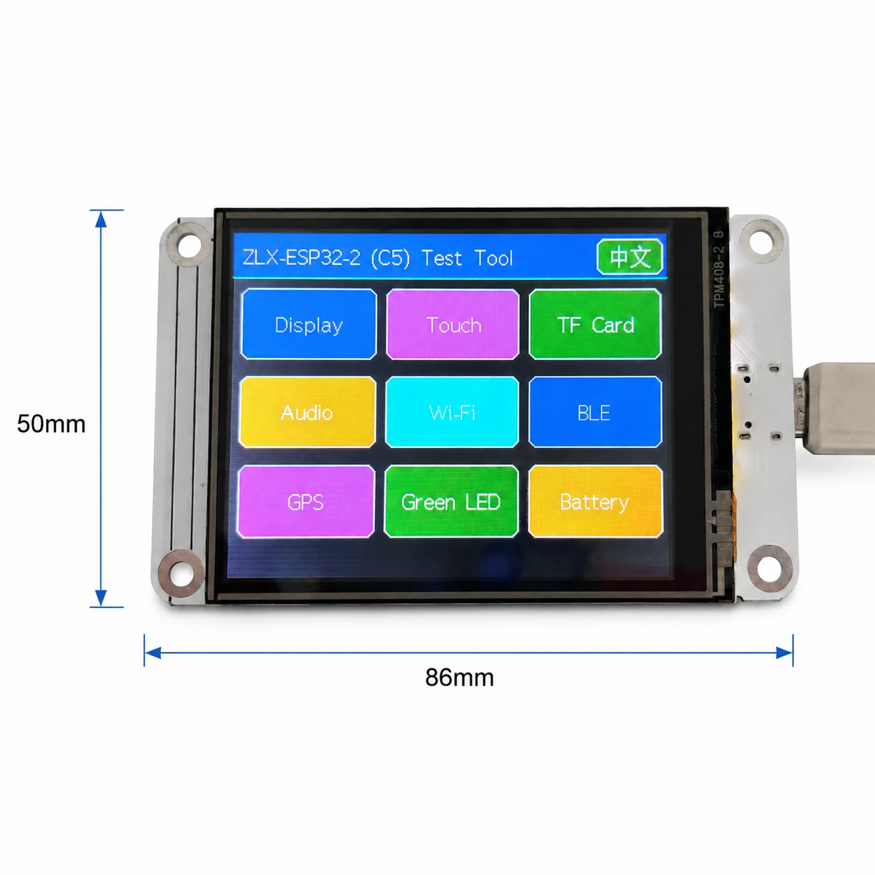
- 2,8 Zoll 240 × 320 LCD-Display, ST7789-Treiberchip, BGR-Initialisierung, Display-Inversionsfunktion ist deaktiviert
- XPT2046 Resistiver Touch-Controller
- Die LCD- und TF-Karte teilen sich eine SPI-Schnittstelle, aber die CS-Schnittstelle ist anders; die Touch-Funktion verwendet eine separate Software-SPI-Schnittstelle.
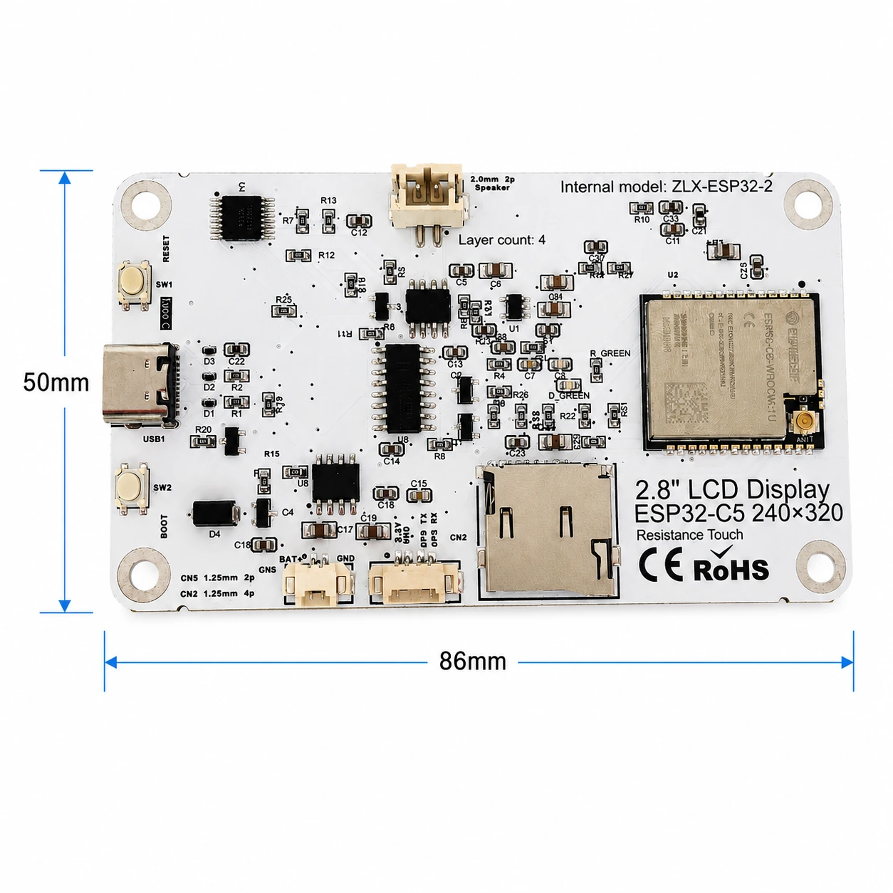
- Bogengröße ca. 86mm x 50mm
- IPEX1 externe Antennenschnittstelle; schließen Sie die entsprechende externe Antenne an, bevor Sie das Radio verwenden.
Zielbenutzer
Für Embedded-Entwickler, IoT-Entwickler, Hersteller, Bildungs-/Laboranwendungen und Produktprototyping.
2. Aussehen und Abmessungen
Die Plattengröße beträgt ca. 86mm x 50mm. Die folgende Abbildung hilft, das Display, die Anschlüsse und die Hauptkomponenten zu identifizieren.
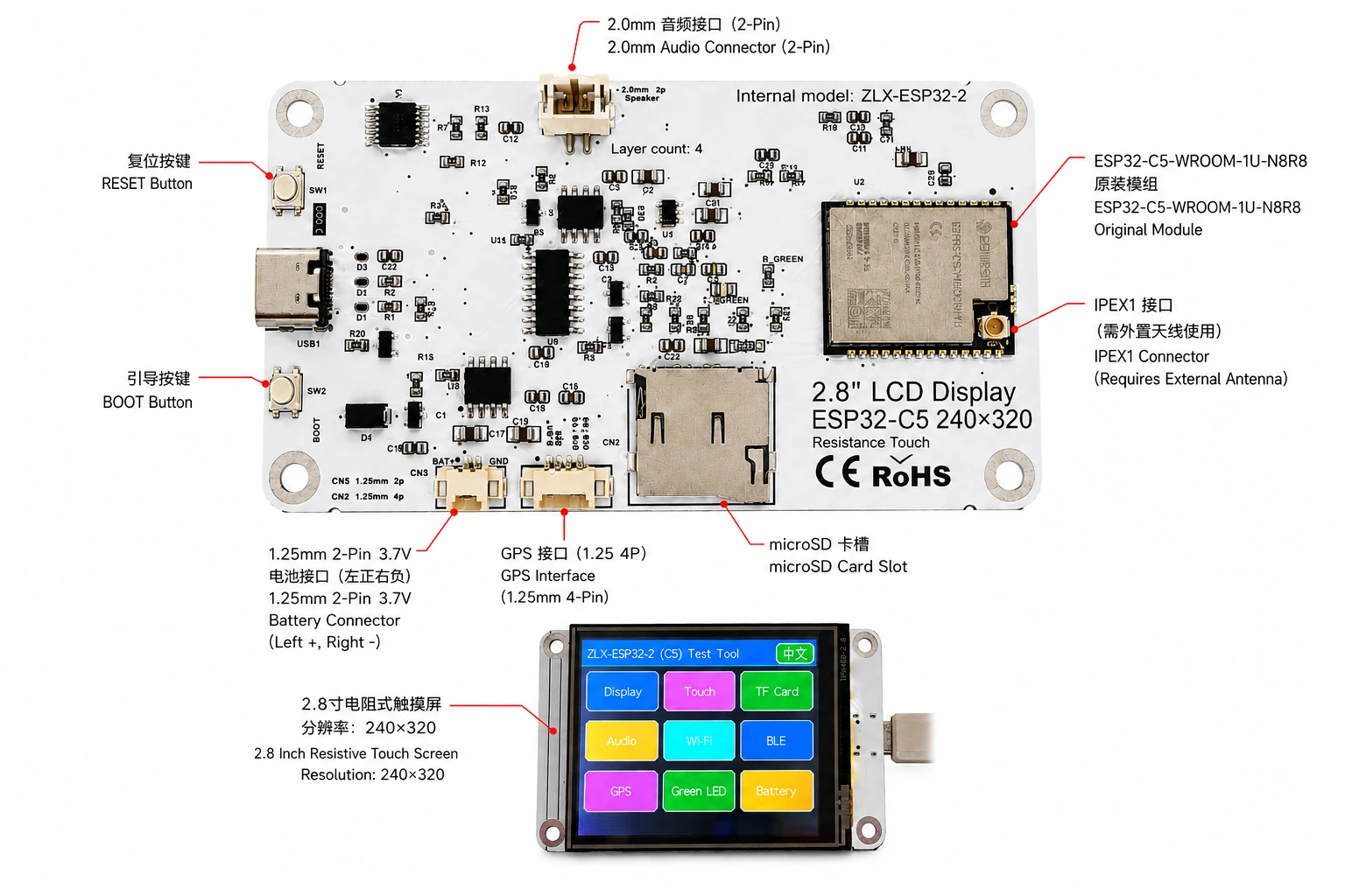
Stecker-Identifikation
3. Leiterplattenspezifikationen
| GEGENSTÄNDE | Format |
|---|---|
| Plattenmodell | ZLX-ESP32-2 |
| Kernmodule | ESP32-C5-WROOM-1U-N8R8 |
| Plattengröße | ca. 86 x 50 mm |
| Darstellung | 2,8 "TFT LCD, ST7789 Chip, Originalauflösung 240 × 320 |
| Farbreihenfolge | BGR-Initialisierung |
| Invertiert anzeigen | Aus/Normaler Anzeigemodus |
| Ausrichten | Resistive Berührung XPT2046 |
| microSD/TF-Kartensteckplatz | SPI-Modus; Karte nicht enthalten |
| GPS-Schnittstelle | 1,25 mm 4-poliger Stecker; UART-Signal an GPIO0/GPIO9 |
| akustisch | 2,0 mm 2-poliger Lautsprecher/Audioanschluss; PWM-Audio + Verstärker aktiviert |
| Batterie | 3,7 V einphasig, 1,25 mm Dual-Pin; mit Schutzschaltung, empfohlene Kapazität 1000-3000 mAh |
| Externe Antenne | IPEX1-Anschluss; erforderlich für drahtlosen WROOM-1U-Pfad |
| Schaltfläche/Button | Reset, Inbetriebnahme |
| Indikatoren: | Grüne LED an GPIO26 |
4. ESP32-C5-WROOM-1U-N8R8 Modulspezifikationen
Die folgenden Schlüsselparameter basieren auf dem offiziellen ESP32-C5-WROOM-1/WROOM-1U-Datenblatt v1.2 von Espressif.
| GEGENSTÄNDE | Format |
|---|---|
| Eingebettete SoCs | ESP32-C5HR8 |
| Hauptprozessor | 32-Bit-RISC-V-Single-Core-Prozessor mit bis zu 240 MHz |
| Rom | 320 KB |
| HP SRAM | 384 KB |
| LP SRAM | 16 KB |
| Blitz | 8 MB Quad Channel SPI |
| PSRAM | 8 MB Quad Channel SPI |
| W-LAN Internet | 1T1R, 2,4 GHz + 5 GHz Dualband; IEEE 802.11ax/ac/b/g/n; bis zu 150 Mbit/s |
| 2,4 GHz Frequenz | 2412–2484 MHz |
| 5-GHz-Frequenz | 5180–5885 MHz (vorbehaltlich lokaler Vorschriften) |
| Bluetooth | Bluetooth Low Energy; Espressif v1.2 Funktionsliste zeigt zertifizierten Bluetooth Core 6.0 |
| IEEE 802.15.4 | 2.4 GHz OQPSK,250 Kbps |
| Zigbee/Thread | Zigbee 3.0 / Thread 1.4 |
| GPIO | Auf Modulebene stehen bis zu 22 GPIOs zur Verfügung. |
| Typical Peripherals | GPIO, SPI, UART, I2C, I2S, RMT, LED PWM, USB Serial/JTAG, MCPWM, GDMA, CAN FD, SDIO slave, ADC, temperature sensor, timers, watchdogs, etc. |
| Module Supply | 3.0–3.6 V, typical 3.3 V |
| Recommended Supply Capability | External supply should be capable of at least 0.6 A for the module |
| Ambient Temperature | -40 to +85 °C |
| Module Size | 18.0 × 21.2 × 3.3 mm |
| Antenna | External antenna via connector/module RF path; 50 Ω RF system |
5. Display and Touch
LCD Parameters
| Item | Specification |
|---|---|
| Size | 2.8 inch |
| Driver IC | ST7789 |
| Native resolution | 240 × 320 |
| Landscape logical resolution | 320 × 240 (depending on rotation setting) |
| Color order | BGR |
| Inversion | Disabled / OFF; normal display mode |
| SPI SCK | GPIO6 |
| SPI MOSI | GPIO7 |
| SPI MISO | GPIO2 (shared with TF card; used if required by library/readback) |
| LCD CS | GPIO10 |
| LCD Backlight | GPIO13 |
| LCD DC / RS | GPIO14 |
Touch Parameters
- Touch type: 4-wire resistive; controller: XPT2046.
- DOUT=GPIO3, SCK=GPIO4, DIN=GPIO5.
- CS=GPIO23, IRQ=GPIO25.
- Touch uses an independent software SPI; the supplied test flow is marked as requiring no calibration.
6. GPIO Mapping
The mapping below is based on the supplied GPIO spreadsheet and cross-checked against the schematic. Board peripherals use 19 GPIOs; TX0=GPIO11 and RX0=GPIO12 are additionally used by UART0; GPIO15 is reserved by PSRAM on N8R8, so all 21 usable GPIOs are allocated; EN is not a GPIO.
| GPIO | Signal | Definition | Direction | Function | Notes |
|---|---|---|---|---|---|
| 0 | GPSTX | GPS UART TX | Input | GPS test | GPS module TX → ESP32-C5 |
| 1 | BAT_ADC | Battery voltage sensing | Input/ADC | Battery test | 100k/100k divider; ADC × 2 ≈ battery voltage |
| 2 | SD_MISO | TF DAT0 / LCD MISO shared | Input | TF card test | Shared SPI MISO |
| 3 | RTP_DOUT | XPT2046 DOUT | Input | Touch test | Touch controller data output |
| 4 | RTP_SCK | XPT2046 SCK | Output | Touch test | Independent software SPI |
| 5 | RTP_DIN | XPT2046 DIN | Output | Touch test | Independent software SPI |
| 6 | LCD_SCK | LCD SCK / TF SCK shared | Output | LCD/TF test | Shared SPI clock |
| 7 | LCD_MOSI | LCD MOSI / TF CMD(MOSI) shared | Output | LCD/TF test | Shared SPI MOSI |
| 8 | AUDIOPWM | Audio PWM | Output | Audio test | Audio output control |
| 9 | GPSRX | GPS UART RX | Output | GPS test | ESP32-C5 TX → GPS module RX |
| 10 | LCDCS | ST7789 CS | Output | Display test | LCD chip select |
| 13 | LCDBL | LCD backlight | Output | Display test | Backlight control |
| 14 | LCD_RS/DC | ST7789 DC | Output | Display test | Data/command select |
| 23 | RTPCS | XPT2046 CS | Output | Touch test | Touch chip select |
| 24 | AMP_EN | Amplifier enable | Output | Audio test | High-level enable per supplied mapping; verify actual hardware revision |
| 25 | RTPIRQ | XPT2046 IRQ | Input | Touch test | Touch interrupt |
| 26 | GREENLED | Green LED | Output | LED test | HIGH = ON, LOW = OFF |
| 27 | SDCS | TF DAT3 / CS | Output | TF card test | TF card SPI chip select |
| 28 | BOOTAUTO | BOOT / auto-start control | Input/Control | Factory restore | BOOT input / factory-restore logic |
System and UART Signals
| Signal | Purpose | Note |
|---|---|---|
| RESET_AUTO / EN | ESP32 reset / enable | System enable/reset; not a GPIO |
| UART0_TX / TX0 / GPIO11 | UART0 transmit | Used; excluded from the 19 peripheral GPIO count |
| UART0_RX / RX0 / GPIO12 | UART0 receive | Used; excluded from the 19 peripheral GPIO count |
7. Interface and Bus Sharing
| Item | GPIO | Description |
|---|---|---|
| LCD + TF Shared SPI | GPIO6 / GPIO7 / GPIO2 | SCK, MOSI, MISO shared; devices separated by independent CS |
| LCD CS | GPIO10 | LCD_CS |
| TF card CS | GPIO27 | SD_CS / DAT3 |
| XPT2046 touch | GPIO3 / 4 / 5 / 23 / 25 | DOUT / SCK / DIN / CS / IRQ |
| GPS UART | GPIO0 / GPIO9 | GPSTX / GPSRX; GPIO0 receives GPS TX, GPIO9 drives GPS RX |
| Battery ADC | GPIO1 | BAT_ADC; 100k/100k divider; C20 100 nF filtering |
| Green LED | GPIO26 | HIGH ON, LOW OFF |
| Audio | GPIO8 / GPIO24 | AUDIOPWM / AMP_EN |
| LCD control | GPIO13 / GPIO14 | Backlight / DC |
SPI Sharing Notes
- LCD and TF card share GPIO6 (SCK), GPIO7 (MOSI), and GPIO2 (MISO), but use GPIO10 (LCD_CS) and GPIO27 (SD_CS) respectively.
- Assert only the target device CS at a time to avoid bus contention.
- The XPT2046 touch controller uses an independent software SPI and does not share the main LCD/TF SCK/MOSI signals.
8. Functional Test Mapping
| Test | GPIO | What is tested | Result / Note |
|---|---|---|---|
| Display | GPIO6, 7, 10, 13, 14, 2 | ST7789 display, 240×320 native / 320×240 landscape; BGR; backlight | Normal / Abnormal |
| Touch | GPIO3, 4, 5, 23, 25 | XPT2046 touch response | Test flow: no calibration |
| TF card | GPIO2, 6, 7, 27 | SPI init, read/write/format | Shares SPI with LCD |
| Audio | GPIO8, 24 | PWM audio and amplifier enable | Continuous playback depends on firmware |
| Wi-Fi | Internal RF | 2.4 GHz / 5 GHz scan | No listed GPIO occupied |
| BLE | Internal RF | BLE scan | No listed GPIO occupied |
| GPS | GPIO0, 9 | GPS UART data | GPSTX / GPSRX |
| LED | GPIO26 | Green LED | HIGH on / LOW off |
| Battery | GPIO1 | ADC measures divided battery voltage | Voltage estimate, not a coulomb counter |
| Factory restore | GPIO28 | BOOT input / restore logic | Behavior is defined by firmware |
9. Connector and Electrical Notes
Battery Connector
The board provides a 1.25 mm 2-pin connector for a single-cell 3.7 V battery. In the orientation shown in the labeled image, the left pin is positive (+) and the right pin is negative (-). For battery-powered operation, use a protected single-cell 3.7 V Li-ion/LiPo battery; 1000–3000 mAh is recommended. Verify connector type and polarity before connection. Reverse polarity may damage the board.
Battery Voltage Sensing
GPIO1 senses battery voltage through a 100 kΩ / 100 kΩ divider, so ideally the battery voltage is approximately 2× the ADC pin voltage. This is a voltage estimate only and is not a fuel-gauge/coulomb-counter measurement.
GPS Interface
GPS uses GPIO0 and GPIO9 as UART signals. In this board mapping, GPIO0 (named GPSTX) is an input connected to the GPS module TX, while GPIO9 (named GPSRX) is an output connected to the GPS module RX. For the 1.25 mm 4-pin connector power pins and exact physical pin order, follow the silkscreen/schematic of the specific hardware revision.
External Antenna
ESP32-C5-WROOM-1U is the external-antenna variant. Connect a suitable 2.4/5 GHz, 50-ohm antenna to the IPEX1 connector. Avoid prolonged high-power transmission without a proper antenna attached.
Audio Connector
Audio output uses GPIO8 (AUDIOPWM) for the PWM signal and GPIO24 (AMP_EN) for amplifier enable. The top connector is a 2.0 mm 2-pin audio/speaker connector. Use loads and volume settings within the capability of the actual amplifier circuit.
10. Software Development and Initialization Notes
- Select ST7789 as the display driver and use 240×320 as the native resolution; set rotation for 320×240 landscape as supported by your graphics library.
- Use BGR color order; do not enable display inversion (INVON).
- When LCD and TF share SPI, manage LCD_CS (GPIO10) and SD_CS (GPIO27) independently after initialization.
- XPT2046 verwendet eigenständige Software SPI auf GPIO3/4/5/23/25.
- Wandeln Sie für die Batteriespannung die GPIO1-ADC-Messwerte mit einem Teilspannungsverhältnis von etwa 2: 1 um und wenden Sie die ADC-Kalibrierung für eine höhere Genauigkeit an.
- Verfügbare 5-GHz-WLAN-Kanäle und Sendeleistung hängen von den örtlichen Vorschriften ab.
- Das Verhalten beim Starten/Wiederherstellen der Werkseinstellungen wird durch die Firmware definiert. Bitte vermeiden Sie eine versehentliche Aktivierung, um ein Löschen der Einstellungen zu vermeiden.
Vorgeschlagener Initialisierungsauftrag
- Wenn die Stromversorgung stabil ist, initialisieren Sie das System und debuggen Sie das UART.
- Initialisieren Sie die LCD-SPI; konfigurieren Sie ST7789, BGR, schalten Sie die Inversion aus und aktivieren Sie die Hintergrundbeleuchtung.
- Initialisieren Sie XPT2046 Touch.
- Wenn ein Wechselspeicher erforderlich ist, legen Sie eine kompatible vom Benutzer bereitgestellte microSD/TF-Karte ein, initialisieren Sie sie und stellen Sie sicher, dass der LCD_CS/SD_CS-Status korrekt ist.
- Initialisieren Sie GPS-, Audio-, LED- und Batterie-ADCs nach Bedarf.
- Aktivieren Sie Wi-Fi/BLE/802.15.4 Radio nach Bedarf.
11. Fehlerbehebung
| Frage | Lösung |
|---|---|
| Leeren/schwarzen Bildschirm anzeigen | Überprüfen Sie GPIO6/7/10/13/14, ST7789 Antriebsauswahl, BGR-Einstellungen, GPIO13 mit Hintergrundbeleuchtung und ob die Invertierung versehentlich aktiviert ist. |
| Farbfehler | Stellen Sie sicher, dass die Grafikbibliothek für die BGR-Farbreihenfolge konfiguriert ist. |
| Keine Berührungsreaktion | Initialisierung von GPIO3/4/5/23/25 und XPT2046 prüfen. |
| TF-Karteninitialisierung fehlgeschlagen | Überprüfen Sie die gemeinsame SPI SCK/Mosi/Miso und stellen Sie sicher, dass SD_CS (GPIO27) und LCD_CS (GPIO10) nicht gleichzeitig eingestellt sind. |
| WLAN-Signal schwach/kein WLAN | Stellen Sie sicher, dass die externe IPEX1-Antenne angeschlossen ist und im GHz-Band 2.4/5 funktioniert. |
| Etwa die Hälfte der Batteriewerte | GPIO1 verwendet einen 100k/100k Spannungsteiler; multiplizieren Sie die ADC-seitige Spannung mit ungefähr 2. |
| Keine GPS-Daten | Stellen Sie sicher, dass GPIO0 GPS TX empfängt, GPIO9 GPS RX antreibt und die Baudrate und Stromversorgung überprüft. |
12. Downloads und technischer Support
Für ZLX-ESP32-2 Firmware, Dokumentation, Follow-up-Dokumentation und damit verbundenen Support besuchen Sie das ZLX ESP32 Development Board Support Center. Stellen Sie vor dem Flashen der Firmware sicher, dass das auf der Website angezeigte PCB-Modell genau mit Ihrer Hardware übereinstimmt.
Downloadlinkshttps://www.zlxchina.xyz/
Lexin Modul Datenblatt: ESP32-C5-WROOM-1/WROOM-1U Datenblatt
Referenz
- ZLX ESP32 Entwicklungsboard Support Center
- Espressif ESP32-C5-WROOM-1 & WROOM-1U Datenblatt v1.2 (2026-08-12)
13. Sicherheit und Betrieb
- Überprüfen Sie die Batteriepolarität vor dem Anschließen; kehren Sie niemals den Batterieanschluss um.
- Wenn Sie den IPEX-Stecker ein- und ausstecken, wenden Sie vertikal Kraft an und vermeiden Sie seitliches Neigen, um eine Beschädigung der HF-Buchse zu vermeiden.
- Bei der Verwendung von nackten Leiterplatten sind elektrostatische Entladungsschutzmaßnahmen zu treffen und Kurzschlüsse durch Metallgegenstände zu vermeiden.
- 5 GHz Funkbänder, Kanäle und Sendeleistung müssen den örtlichen Vorschriften entsprechen.
- Befolgen Sie für TF-Karten, GPS, Audio und andere Peripheriegeräte die in der tatsächlichen Hardwareversion angegebenen Leistungs- und Logikpegel. Wenden Sie keinen Logikpegel von mehr als 3,3 V an E/A-Pins an, es sei denn, dies wurde ausdrücklich überprüft.
14. Änderungshistorie des Dokuments
| Pastor | Datum | Beschreibung | Grundlagen |
|---|---|---|---|
| V1.1 | 2026-08-25 | Überarbeitete Anweisungen für microSD/TF-Karten, Batterien und GPIO. | Hefei Zhiluxing Information Technology Co., Ltd. |
Ende