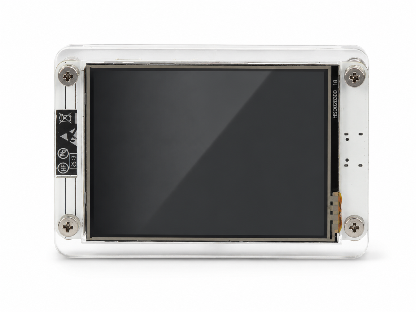
ESP32-2432S0248R-PLUS
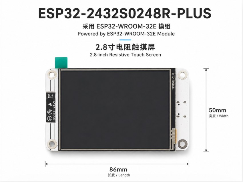
Product Overview
ESP32-2432S0248R-PLUS is a ESP32-WROOM-32E The 2.8-inch color touch screen development board developed by the wireless communication module integrates LCD display, XPT2046 resistive touch, Type-C, TF card, RGB indicator, serial port and expansion interface.
ESP32-2432S0248R-PLUS is a 2.8-inch touch display development board based on the ESP32-WROOM-32E wireless module, integrating LCD display, XPT2046 resistive touch, Type-C, TF card, RGB LED, UART and expansion ports.
Scenarios/Applications
It is suitable for IoT control terminals, smart home control panels, industrial data display, sensor acquisition and display, teaching experiments, Wi ‑ Fi/Bluetooth interactive interfaces and other projects.
Suitable for IoT terminals, smart home panels, industrial data display, sensor monitoring, education, and Wi‑Fi / Bluetooth HMI projects.
Interface Callout/Interface Layout
Customer Presentation Chart in Chinese and English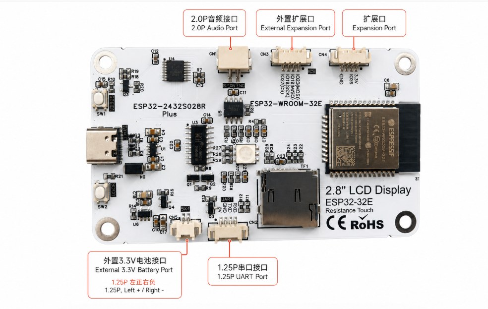
Package Contents
Acrylic version/without acrylic version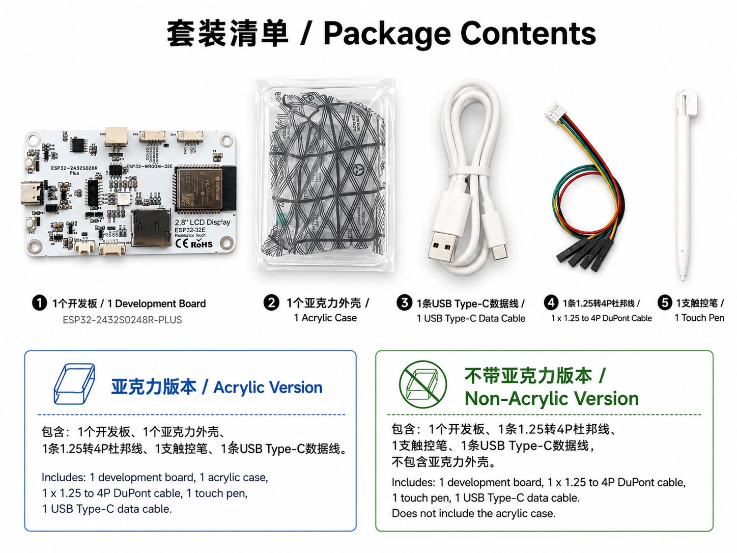
Product Features/Key Features
Product HighlightsDisplay & Touch
2.8 inch TFT LCD, resolution 240 × 320, LCD driver ST7789, initialization recommended BGR Color Sequence; Touch chip with XPT2046(XP2046) Resistance touch scheme.
2.8-inch TFT LCD, 240 × 320 resolution, ST7789 LCD driver with recommended BGR initialization; XPT2046 resistive touch controller.
Wireless & Expansion
ESP32-WROOM-32E supports 2.4GHz Wi ‑ Fi, Bluetooth/BLE, onboard TF card holder, RGB indicator, serial interface, audio interface and extension interface for secondary development.
ESP32-WROOM-32E supports 2.4GHz Wi‑Fi, Bluetooth / BLE. The board includes TF card slot, RGB LED, UART, audio and expansion ports.
Basic Parameters/Basic Specifications
Hardware Specification| Project Item | Parameters/Specification |
|---|---|
| Product Model/Model | ESP32-2432S0248R-PLUS |
| Main Module | ESP32-WROOM-32E |
| Wireless | 2.4GHz Wi‑Fi 802.11 b/g/n, Bluetooth / BLE |
| Display | 2.8-inch TFT LCD, 240 × 320 |
| LCD Driver | ST7789, BGR initialization/ST7789 with BGR initialization |
| Touch Type | Resistive Touch |
| Touch Chip/Touch Controller | XPT2046 / XP2046 |
| USB Interface/USB Port | USB Type ‑ C, power supply, download, serial debugging/Power, programming and serial debugging |
| Storage Interface/Storage | TF / MicroSD Card Slot |
| Buttons | SW1, SW2 |
| Lights/Indicator | On-board RGB LED |
| Card size/Board Size | 86mm × 50mm |
| Logic Level | 3.3V |
| Power Supply / Power Supply | USB Type‑C 5V input / external 3.3V battery port |
| Development environment / Development | Arduino IDE, PlatformIO, ESP-IDF, MicroPython compatible |
ESP32-WROOM-32E Module Parameters
Core Module| Project Item | Parameters/Specification |
|---|---|
| Module model / Module | ESP32-WROOM-32E |
| CPU | Xtensa® dual-core 32-bit LX6, up to 240MHz / up to 240MHz |
| ROM / SRAM | 448KB ROM, 520KB SRAM, 16KB RTC SRAM |
| Flash | Standard 4MB Flash, subject to batch configuration / Standard 4MB Flash, subject to batch configuration |
| Wi‑Fi | 802.11 b/g/n,2.4GHz |
| Bluetooth | Bluetooth v4.2 BR/EDR and Bluetooth LE |
| Antenna / Antenna | On-board PCB antenna / On-board PCB antenna |
| GPIO | The module can provide multiple GPIOs, and the actual available pins depend on board mapping. |
| Module Size / Module Size | 18.0mm × 25.5mm × 3.1mm |
Interface Description / Interface Description
Connector FunctionsUSB Type‑C
Used for development board power supply, program download and serial port debugging.
Used for power supply, firmware programming and serial debugging.
2.0P Audio Interface/Audio Port
Audio-related interfaces are reserved and can be used for audio input/output or power amplifier-related applications. The specific functions are defined by the user program.
Reserved for audio input/output or amplifier-related applications depending on user firmware.
External Expansion Port
SPI/GPIO expansion signals are reserved for easy connection to external sensors, peripheral modules or user-defined expansion boards.
Reserved SPI / GPIO expansion signals for external sensors, modules or custom boards.
External 3.3V battery interface/Battery Port
The interface specification is 1.25P, with the positive pole on the left and the negative pole on the right. Do not connect it reversely and do not input 5V.
1.25P connector. Left pin is positive, right pin is negative. Do not reverse polarity or input 5V.
1.25P serial port interface/UART Port
Used for serial communication, debugging or external serial port modules.
Used for UART communication, debugging or external serial modules.
TF card holder / TF Card Slot
It can be used for applications such as data storage, image resource storage, and configuration file reading.
Used for data storage, image resources and configuration files.
GPIO Mapping Table / GPIO Mapping Table
From Uploaded Mapping Sheet| Module / Module | Signal/Silk screen / Signal | GPIO | Code Macro / Macro | Direction / Direction | Description / Description |
|---|---|---|---|---|---|
| master control | RESET | EN | LCD_RST=-1 | Input reset | Connect to ESP32 EN and do not occupy GPIO Connected to ESP32 EN; does not occupy a GPIO. |
| LCD/ST7789 | LCD_SCK | GPIO14 | LCD_SCK=14 | output | LCD SPI clock VSPI LCD SPI clock, VSPI bus. |
| LCD/ST7789 | LCD_MISO | GPIO12 | LCD_MISO=12 | enter | LCD SPI MISO ST7789 does not read the screen by default LCD SPI MISO; ST7789 normally does not require screen readback. |
| LCD/ST7789 | LCD_MOSI | GPIO13 | LCD_MOSI=13 | output | LCD SPI MOSI LCD SPI MOSI data line. |
| LCD/ST7789 | LCD_RS / DC | GPIO2 | LCD_RS=2 | output | LCD data/command selection pin LCD data/command select pin. |
| LCD/ST7789 | LCD_CS | GPIO15 | LCD_CS=15 | output | LCD chip select LCD chip select. |
| LCD/ST7789 | LCD_BL | GPIO21 | LCD_BL=21; BACKLIGHT_PIN=21 | output | LCD backlight control LCD backlight control. |
| Touch/XPT2046 | RTP_IRQ / SENSOR_VP | GPIO36 | RTP_IRQ=36; TOUCH_IRQ=36 | enter | Touch interrupt input dedicated pin Touch interrupt; input-only GPIO. |
| Touch/XPT2046 | RTP_DOUT / SENSOR_VN | GPIO39 | RTP_DOUT=39; TOUCH_MISO=39 | enter | Touch SPI DOUT/MISO input dedicated pin Touch SPI DOUT/MISO; input-only GPIO. |
| Touch/XPT2046 | RTP_DIN | GPIO32 | RTP_DIN=32; TOUCH_MOSI=32 | output | Touch SPI DIN/MOSI Touch SPI DIN/MOSI. |
| Touch/XPT2046 | RTP_CS | GPIO33 | RTP_CS=33; TOUCH_CS=33 | output | Touch chip selection Touch chip select. |
| Touch/XPT2046 | RTP_SCK | GPIO25 | RTP_SCK=25; TOUCH_CLK=25 | output | Touch SPI clock Touch SPI clock. |
| Battery | BAT_ADC | GPIO34 | BAT_ADC=34; BAT_ADC_PIN=34 | enter | Battery voltage ADC input dedicated pin Battery voltage ADC; input-only GPIO. |
| RGB tri-color light | RGB_R | GPIO17 | RGB_LED_R=17 | output | Onboard RGB red channel records by RGB=17/22/16 On-board RGB LED red channel; RGB=17/22/16. |
| RGB tri-color light | RGB_G | GPIO22 | RGB_LED_G=22 | output | Onboard RGB green channel records by RGB=17/22/16 On-board RGB LED green channel; RGB=17/22/16. |
| RGB tri-color light | RGB_B | GPIO16 | RGB_LED_B=16 | output | Onboard RGB blue channel records by RGB=17/22/16 On-board RGB LED blue channel; RGB=17/22/16. |
| Audio | AUDIO_IN | GPIO26 | AUDIO_IN=26 | Input/ADC | Audio input reserved Reserved audio input. |
| Audio | AUDIO_EN | GPIO4 | AUDIO_EN=4 | output | Audio/power amplifier enable reserved Reserved audio/amplifier enable control. |
| Extended SPI | SPI_CS | GPIO27 | SPI_CS=27 | output | Extended SPI chip select reserved Reserved expansion SPI chip select. |
| SD card | SD_MOSI | GPIO23 | SD_MOSI=23 | output | SD SPI MOSI reserved Reserved SD SPI MOSI. |
| SD card | SD_MISO | GPIO19 | SD_MISO=19 | enter | SD SPI MISO Reserved Reserved SD SPI MISO. |
| SD card | SD_SCK | GPIO18 | SD_SCK=18 | output | SD SPI clock reservation Reserved SD SPI clock. |
| SD card | SD_CS | GPIO5 | SD_CS=5 | output | SD card is reserved Reserved SD card chip select. |
Package Versions / Package Versions
Acrylic / Non-AcrylicAcrylic Version / Acrylic Version
- 1 Development Board / 1 Development Board
- 1 Acrylic Case / 1 Acrylic Case
- 1 x 1.25 to 4P DuPont Cable / 1 × 1.25 to 4P DuPont Cable
- 1 stylus / 1 Touch Pen
- 1 USB Type‑C Data Cable / 1 USB Type‑C Data Cable
Non-Acrylic Version / Non-Acrylic Version
- 1 Development Board / 1 Development Board
- 1 x 1.25 to 4P DuPont Cable / 1 × 1.25 to 4P DuPont Cable
- 1 stylus / 1 Touch Pen
- 1 USB Type‑C Data Cable / 1 USB Type‑C Data Cable
- Does not include acrylic case / Does not include acrylic case
Recommended initialization configuration / Recommended Initialization
ST7789 BGR + XPT2046TFT_eSPI Example Configuration / TFT_eSPI Example
#define ST7789_DRIVER
#define TFT_WIDTH  240
#define TFT_HEIGHT 320

#define TFT_MISO 12
#define TFT_MOSI 13
#define TFT_SCLK 14
#define TFT_CS   15
#define TFT_DC   2
#define TFT_RST  -1

#define TFT_BL   21
#define TFT_BACKLIGHT_ON HIGH

// Important: use BGR color order
#define TFT_RGB_ORDER TFT_BGR

#define SPI_FREQUENCY 40000000
XPT2046 Touch Configuration / Touch Example
#define TOUCH_IRQ   36
#define TOUCH_MISO  39
#define TOUCH_MOSI  32
#define TOUCH_CS    33
#define TOUCH_CLK   25
Precautions for use/Notes
Important1. The GPIO logic level is 3.3V, please do not directly connect to 5V signals. / GPIO logic level is 3.3V. Do not connect 5V signals directly.
2. Please pay attention to the direction of the positive and negative poles of the external 3.3V battery interface, left is positive and right is negative. / External 3.3V battery port: left positive, right negative.
3. GPIO34, GPIO36, and GPIO39 are dedicated input pins and cannot be used as ordinary outputs. / GPIO34, GPIO36 and GPIO39 are input-only pins.
4. The LCD uses ST7789 driver, and it is recommended to set it to BGR color sequence; if the color is abnormal, please check the RGB/BGR settings. / ST7789 BGR color order is recommended. If colors are wrong, check RGB/BGR setting.
5. The touch chip is XPT2046, and touch calibration is recommended after the screen is rotated. / XPT2046 touch may require calibration after display rotation.
Data download / Resources Download:https://www.zlxchina.xyz/
Instructions/Note: If product parameters, accessory lists and interface definitions are subject to batch adjustments, please refer to the actual product and official data download page. Product specifications, package contents and pin definitions may vary by batch; please refer to the actual product and official download page.