ESP32-2432S0248R-PLUS Product Specification/Product Manual | Data download/download address: https://www.zlxchina.xyz/ |
Data download address/ Resource download:https://www.zlxchina.xyz/ |
ESP32-2432S0248R-PLUS
2.8inch resistive touch screen development board/ 2.8-inch resistive touch screen development board
useESP32-WROOM-32UEmodule/ Powered by ESP32-WROOM-32UEmodule
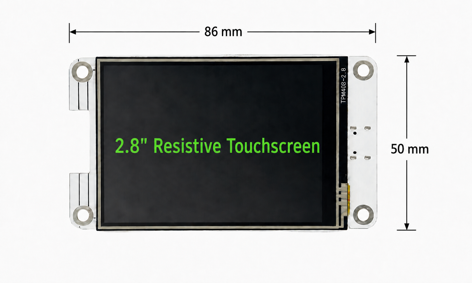
Product front size chart/ Front dimension drawing
2.8inch touch screen 2.8-inch resistive touchscreen with 240 x 320 resolution | ESP32-WROOM-32UE 2.4GHz Wi-Fi + Bluetooth/BLE wireless module |
ST7789 + BGR LCD driver uses ST7789 and is initialized with BGR color sequence | XPT2046 touch chip Touch controller: XPT2046/XP2046 compatible naming |
■ 1. Product overview / Product Overview
ESP32-2432S0248R-PLUS is a product based onESP32-WROOM-32UEWireless communication module developed2.8 inch color touch screen development board, integratedLCD display, touch input, TF Card, USB Type-C , serial port, battery interface and multiple sets of expansion interfaces, suitable for IoT display terminals, smart home control, human-computer interaction interface, experiments and serial port project development.
ESP32-2432S0248R-PLUS is a device based onESP32-WROOM-32UE2.8-inch color touch display development board for wireless module. It integrates LCD display, touch input, TF card slot, USB Type-C interface, UART interface, battery interface and a variety of expansion interfaces, and is suitable for IoT terminals, smart home control, human-machine interface panels, education and embedded development and other fields.
▌2 . Main features / Main features
project/project | parameter/Specification |
Main control module/main control module | ESP32-WROOM-32UE |
Wireless function/Wireless | 2.4GHz Wi-Fi 802.11 b/g/n; Bluetooth/BLE |
display/monitor | 2.8-inch TFT LCD display, resolution 240 x 320 |
touch/touch | Resistive touch, XPT2046 touch controller |
Display driver/LCD driver | ST7789, BGR color sequence initialization |
Expansion capabilities/expansion | UART, TF card, GPIO/SPI expansion, audio port |
▌ 3. Basic parameters /Basic specifications
project/project | parameter/Specification |
Product model/model | ESP32-2432S0248R-PLUS |
Main control module/main control module | ESP32-WROOM-32UE |
Screen Size / Screen Size | 2.8 inches |
screen type / screen type | TFT LCD display + resistive touch screen |
resolution/resolution | 240 x 320 |
LCD driver / LCD driver | ST7789 |
display initialization/display initialization | ST7789 BGR color sequence / ST7789 BGR color sequence initialization |
Touch chip/Touch controller | XPT2046 / XP2046 |
Card size/Board Size | 86mm x 50mm |
Power supply/power supply | USB Type-C 5V input; external 3.3V battery interface |
logic level/logic level | 3.3 volts |
Data download/resource download | https://www.zlxchina.xyz/ |
■ 4. ESP32-WROOM-32UE moduleparameter/ ESP32-WROOM-32UEModule parameters
project/project | parameter/Specification |
Module model/module | ESP32-WROOM-32UE |
Chip core/CPU core | Xtensa Dual Core 32-bit LX6 |
Main frequency/clock frequency | Up to 240MHz |
read-only memory | 448KB |
SRAM | 520KB |
RTC SRAM | 16KB |
Blink | Typical board configuration: 4MB flash; actual batches may vary |
Wireless LAN | 2.4GHz,802.11 b/g/n |
Bluetooth | Bluetooth BR/EDR and Bluetooth Low Energy |
antenna/antenna | Onboard PCB antenna |
working voltage / working voltage | Module supply voltage range is 3.0V to 3.6V; board level logic voltage is 3.3V |
Module Size / Module Size | 18.0mm x 25.5mm x 3.1mm |
▌ 5. Screen and touch instructions / Display and touch instructions
This product uses2.8 inch resistive touch screen, the touch chip adoptsXPT2046 (Some information also includesXP2046 )。LCDdriven byST7789 , it is recommended to use the program initializationBGR color sequence. If the display color appears red and blue, please checkTFT_RGB_ORDER / BGRInitialize configuration.
This product uses a 2.8-inch resistive touch screen and is equipped with an XPT2046 touch controller. The LCD driver is ST7789 and should be initialized with BGR color sequence. If red and blue swap, check the RGB/BGR settings in your display driver.
▌ 6. Recommended initial configuration /Recommended initialization configuration
// TFT display / ST7789 |
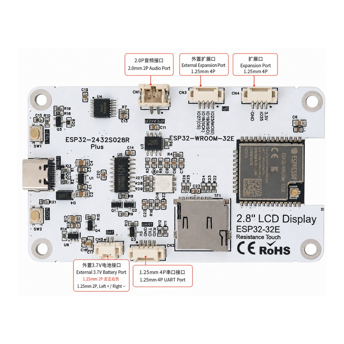
■ 7. Interface annotation /interface overview
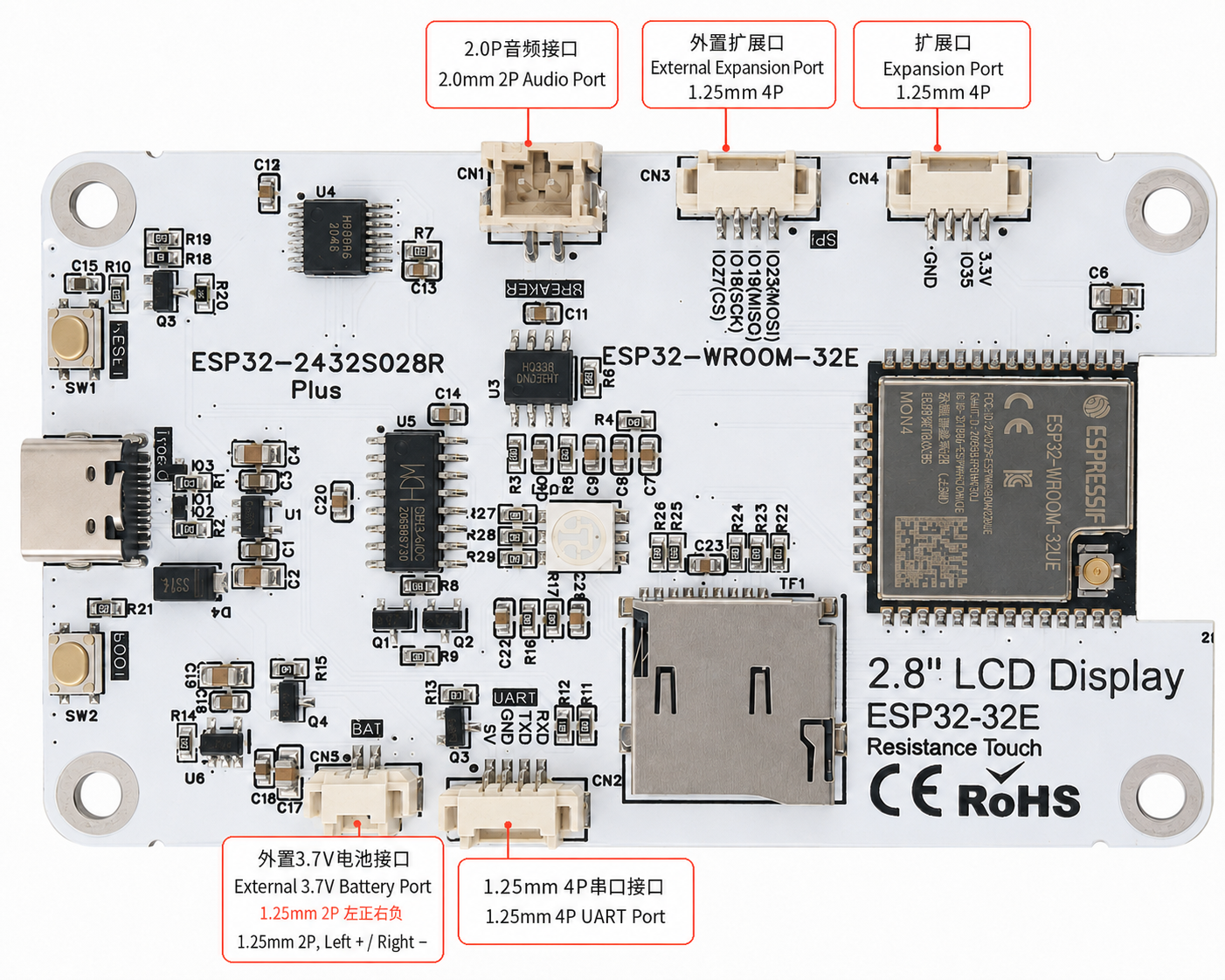
Interface labeling on the back of the development board/Back interface label
project/project | parameter/Specification |
2.0P audio interface /2.0P audio interface | Audio ports are reserved for audio input/output or amplifier related expansion as defined by the firmware. |
External expansion port/External Expansion Port | Reserved external expansion interface for SPI/GPIO peripherals, sensors or custom modules. |
Expansion port/Expansion port | Reserve 3.3V, GND and GPIO signals for external low-power modules. |
External 3.3V battery interface /External 3.3V battery interface | 1.25P connector, left + / right -. Do not reverse the polarity and do not input 5V power. |
1.25P serial port / 1.25P UART port | UART communication and debug port. |
TF card holder/TF card slot | MicroSD/TF card slot for data, image or configuration storage. |
■ 8. Set list /package contents
■ 9. GPIOmapping table /GPIO mapping table
The following mapping table is based on this productGPIO Mapping table arrangement. Please confirm the interface direction, voltage and function reuse relationship before developing the program.
The following table is based on the GPIO mapping of this product. Please confirm pin orientation, voltage levels, and multiplexing capabilities before development.
module | Signal/silk screen | ESP32 GPIO | code macro | direction | illustrate |
master control | reset | EN | LCD_RST=-1 | Input reset | Connected to ESP32 EN does not occupy GPIO |
LCD/ST7789 | LCD_SCK | GPIO14 | LCD_SCK=14 | output | LCD SPI clock VSPI |
LCD/ST7789 | LCD_MISO | GPIO12 | LCD_MISO=12 | enter | LCD SPI MISO ST7789 does not read the screen by default |
LCD/ST7789 | LCD_MOSI | GPIO13 | LCD_MOSI=13 | output | LCD SPI MOSI |
LCD/ST7789 | LCD_RS / DC | GPIO2 | LCD_RS=2 | output | LCD data/command selection pin |
LCD/ST7789 | LCD_CS | GPIO15 | LCD_CS=15 | output | LCD chip selection |
LCD/ST7789 | LCD_BL | GPIO21 | LCD_BL=21; backlight pin=21 | output | LCD asset control |
Touch/XPT2046 | RTP_IRQ / SENSOR_VP | GPIO36 | RTP_IRQ=36;TOUCH_IRQ=36 | enter | Touch interrupt input dedicated pin |
Touch/XPT2046 | RTP_DOUT / SENSOR_VN | GPIO39 | RTP_DOUT=39;TOUCH_MISO=39 | enter | Touch SPI DOUT/MISO input dedicated pin |
Touch/XPT2046 | RTP_DIN | GPIO32 | RTP_DIN=32;TOUCH_MOSI=32 | output | Touch SPI DIN/MOSI |
Touch/XPT2046 | RTP_CS | GPIO33 | RTP_CS=33;TOUCH_CS=33 | output | Touch chip selection |
Touch/XPT2046 | RTP_SCK | GPIO25 | RTP_SCK=25; TOUCH_CLK=25 | output | Touch SPI clock |
■ 9. GPIOMapping table (continued) /GPIO mapping table-continued
module | Signal/silk screen | ESP32 GPIO | code macro | direction | illustrate |
Battery | Battery_ADC | GPIO34 | BAT_ADC=34;BAT_ADC_PIN=34 | enter | Battery voltage ADC input dedicated pin |
RGB tri-color light | RGB_R | GPIO17 | RGB_LED_R=17 | output | Onboard RGB red channel records according to RGB=17/22/16 |
RGB tri-color light | RGB_G | GPIO22 | RGB_LED_G=22 | output | Onboard RGB green channel records according to RGB=17/22/16 |
RGB tri-color light | RGB_B | GPIO16 | RGB_LED_B=16 | output | Onboard RGB blue channel records according to RGB=17/22/16 |
Audio | audio input | GPIO26 | audio input=26 | Input/ADC | Audio input R&D |
Audio | Audio_English | GPIO4 | AUDIO_EN=4 | output | Audio/Amplifier Enabled Construction |
Extended SPI | SPI_CS | GPIO27 | SPI_CS=27 | output | Extended SPI chip select items |
SD card | SD_MOSI | GPIO23 | SD_MOSI=23 | output | SD SPI MOSI preliminary preparation |
SD card | SD_MISO | GPIO19 | SD_MISO=19 | enter | SD SPI MISO R&D |
SD card | SD_SCK | GPIO18 | SD_SCK=18 | output | SD SPI clock preparation |
SD card | SD_CS | GPIO5 | SD_CS=5 | output | SD preparation plan |
■ 10. Precautions for use /Important Note
project/project | parameter/Specification |
GPIO level/GPIO level | The GPIO logic level of the development board is 3.3V, please do not directly connect to the 5V signal. /GPIO logic level is 3.3V. Do not connect the 5V signal directly. |
Input dedicated pin/Input pin only | GPIO34, GPIO36, and GPIO39 are dedicated input pins and cannot be used as ordinary outputs. / GPIO34, GPIO36 and GPIO39 are input-only pins and cannot be used as outputs. |
Battery interface/battery port | The external 3.3V battery interface is positive on the left and negative on the right. Reverse connection or 5V input is strictly prohibited. /The external 3.3V battery interface is left +/right -. Do not connect reverse polarity or input 5V. |
Touch Controller/Touch Calibration | After the screen is rotated or the coordinate direction changes, please perform touch adjustment again. / Recalibrate touch after display rotation or coordinate orientation change. |
display color/display color | If the colors are reversed between red and blue, please check the ST7789 BGR/RGB initialization settings. / If colors are swapped, check ST7789 BGR/RGB initialization settings. |
Data download/download | https://www.zlxchina.xyz/ |
▌11 . Typical applications /Typical applications
Smart Home Control Panel/Smart Home Control Panel | IoT data display terminal / IoT data display terminal |
Industrial equipment status display / Industrial equipment status display | Sensor data display/Sensor data display |
Wi-Fi/Bluetooth control terminal/Wireless control terminal | Teaching experiment development board/education development board |
▌12 . Technical support /technical support
Development materials, sample programs, solidification, GPIO The mapping table and update files can be obtained at the following address:
Data download/ Resource download:https://www.zlxchina.xyz/