ZLX-ESP32-2
ESP32-C5 2.8-inch Touch Display Development Board
Manual de usuario en chino e inglés. / Bilingual User Manual
Model / modelo: ZLX-ESP32-2
Module / módulo: ESP32-C5-WROOM-1U-N8R8
Document Version / Versión del documento: V1.1 | 2026-08-25
1. Descripción general del producto / 1. Product Overview
ZLX-ESP32-2 es un producto basado en ESP32-C5-WROOM-1U-N8R8 Modular 2.8 Placa de desarrollo de pantalla táctil resistiva de pulgadas con color integrado LCD、XPT2046 tocar,microSD/TF Ranura para tarjetas (solo ranura para tarjetas, no incluida) microSD/TF Tarjeta),GPS Interfaz, salida de audio, detección de voltaje de batería, verde LED、BOOT/RESET Botón e interfaz de antena externa. Adecuado Wi-Fi 6、Bluetooth LE、Zigbee/Thread, interfaz hombre-máquina, registro de datos y desarrollo de aplicaciones de Internet de las cosas.
ZLX-ESP32-2 is a 2.8-inch resistive-touch development board based on the ESP32-C5-WROOM-1U-N8R8 module. It integrates a color LCD, XPT2046 touch controller, a microSD/TF card slot (slot only; no microSD/TF card is included), GPS interface, audio output, battery-voltage sensing, green LED, BOOT/RESET buttons, and an external-antenna connector. It is suitable for Wi-Fi 6, Bluetooth LE, Zigbee/Thread, HMI, data logging, and IoT development.
Características principales / Key Features
ESP32-C5 32 Poco RISC-V Procesador de un solo núcleo, hasta 240 MHz / ESP32-C5 32-bit RISC-V single-core CPU, up to 240 MHz
ESP32-C5-WROOM-1U-N8R8:8 MB Flash + 8 MB PSRAM(Módulo de recursos integrados, no microSD/TF Tarjeta) / ESP32-C5-WROOM-1U-N8R8: 8 MB Flash + 8 MB PSRAM (onboard module memory, not a microSD/TF card)
2.4 GHz + 5 GHz doble banda Wi-Fi 6(802.11ax) / 2.4 GHz + 5 GHz dual-band Wi-Fi 6 (802.11ax)
Bluetooth LE、IEEE 802.15.4、Zigbee 3.0、Thread 1.4 / Bluetooth LE, IEEE 802.15.4, Zigbee 3.0, Thread 1.4
2.8 pulgada 240×320 LCD,ST7789 conducir,BGR Inicialización, deshabilitar el color inverso / 2.8-inch 240×320 LCD, ST7789 driver, BGR initialization, display inversion disabled
XPT2046 Controlador táctil resistivo / XPT2046 resistive touch controller
LCD y TF Compartir tarjeta SPI autobús, independiente CS;Toque para usar el software independiente SPI / LCD and TF card share SPI with separate CS; touch uses an independent software SPI
Tamaño del tablero aprox. 86 mm × 50 mm / Board size approx. 86 mm × 50 mm
IPEX1 Interfaz de antena externa; La antena externa debe estar conectada correctamente antes de utilizar la función inalámbrica. / IPEX1 external antenna connector; connect a suitable external antenna before radio use
Objetos aplicables / Intended Users
Adecuado para desarrolladores integrados, desarrolladores de IoT, creadores, experimentos de enseñanza y diseño de prototipos de productos.
For embedded developers, IoT developers, makers, education/lab use, and product prototyping.
2. Apariencia y tamaño / 2. Appearance and Dimensions
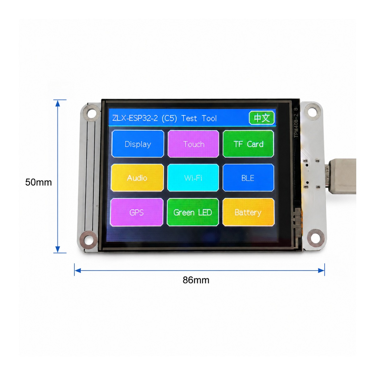
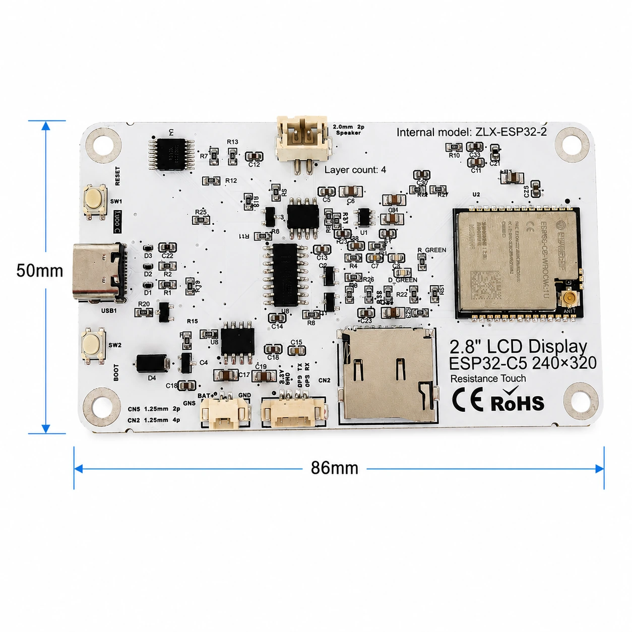
Las dimensiones totales del tablero son aproximadamente 86 mm × 50 mm. Las siguientes imágenes del anverso y el reverso se utilizan para identificar la pantalla, las interfaces y los componentes principales.
The board outline is approximately 86 mm × 50 mm. The images below help identify the display, connectors, and major components.
|
|
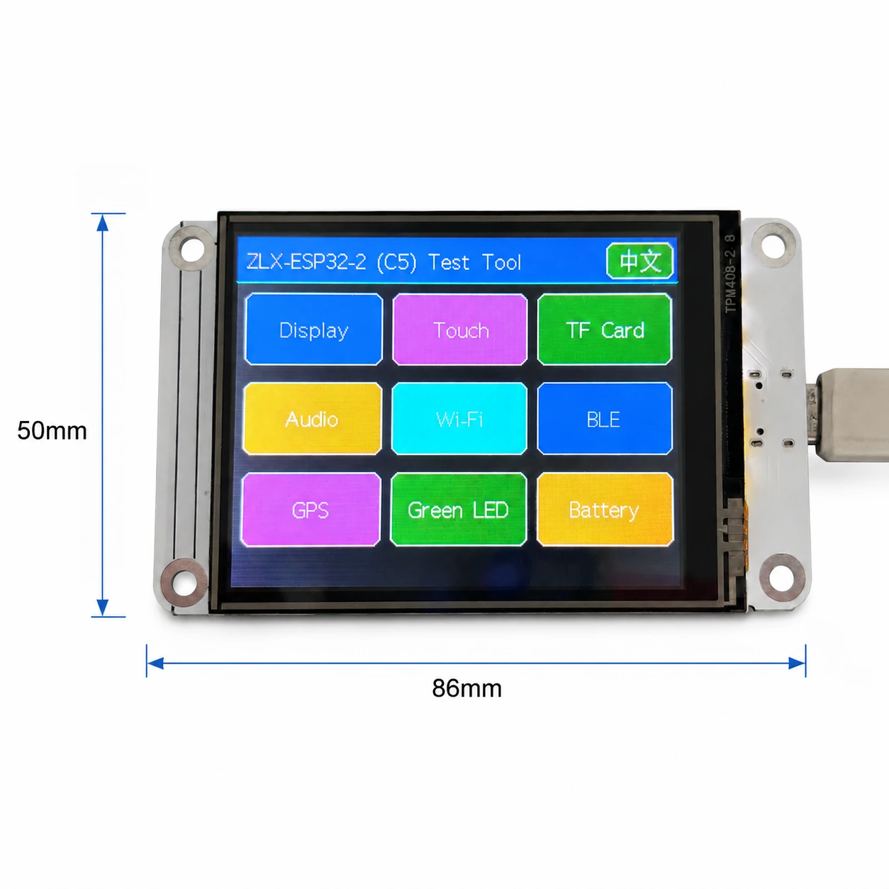
imagen 1 Dimensiones frontal y pantalla / Figure 1 Board front and display-side dimensions
Anotación de interfaz / Connector Identification
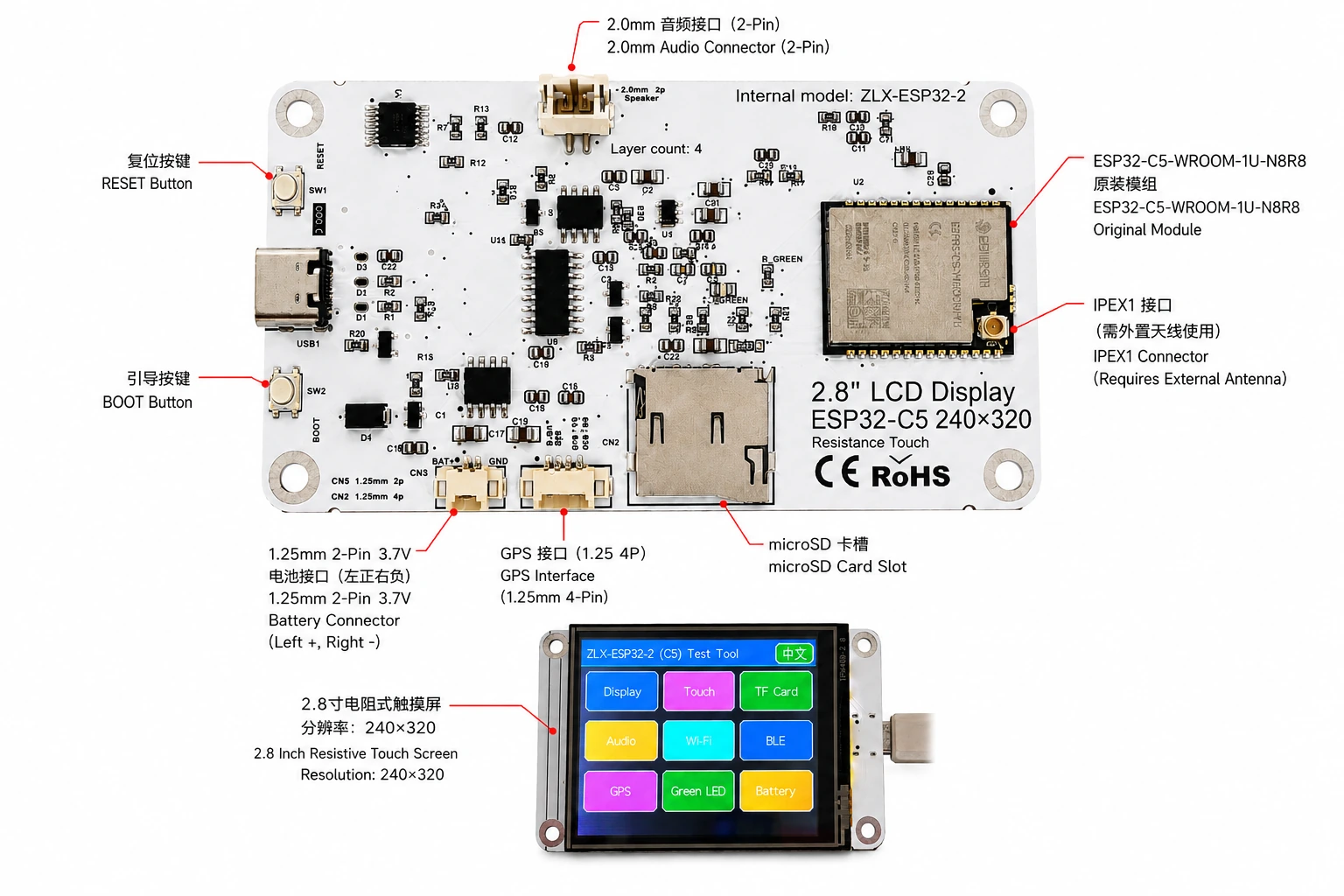
imagen 2 ZLX-ESP32-2 Anotaciones de interfaz en chino e inglés / Figure 2 Bilingual connector identification
3. Especificaciones de la placa de desarrollo / 3. Board Specifications
proyecto / Item | Especificación / Specification |
Modelo de placa de desarrollo / Board model | ZLX-ESP32-2 |
módulo central / Core module | ESP32-C5-WROOM-1U-N8R8 |
Tamaño del tablero / Board size | Approx. 86 × 50 mm |
Mostrar / Display | 2.8-inch TFT LCD, ST7789, 240×320 native resolution |
orden de color / Color order | BGR initialization |
Mostrar color inverso / Display inversion | OFF / Normal display mode(No active el color inverso) |
tocar / Touch | Resistive touch / Toque resistivo, XPT2046 |
microSD/TF ranura para tarjeta / microSD/TF Card Slot | SPI mode; card not included / SPI modo; no viene con tarjeta |
GPS interfaz / GPS interface | 1.25 mm 4-pin connector; UART signals on GPIO0/GPIO9 |
interfaz de audio / Audio | 2.0 mm 2-pin speaker/audio connector; PWM audio + amplifier enable |
Interfaz de batería / Battery | 3.7 V 1S, 1.25 mm 2-pin; protected 1000–3000 mAh recommended / sección única 3.7 V;sugerencia 1000–3000 mAh Con tablero protector |
antena externa / External antenna | IPEX1 connector; required for the WROOM-1U radio path |
botón / Buttons | RESET, BOOT |
indicación de estado / Indicator | Green LED on GPIO26 |
ilustrar / Note: La resolución de pantalla nativa es 240×320;Cuando el software está configurado para rotación de pantalla horizontal, el tamaño lógico de la pantalla se puede expresar como 320×240。 / The panel native resolution is 240×320; in landscape rotation, the logical display size may be 320×240.
4. ESP32-C5-WROOM-1U-N8R8 Parámetros del módulo / 4. ESP32-C5-WROOM-1U-N8R8 Module Specifications
Los siguientes parámetros clave se basan en Espressif oficial ESP32-C5-WROOM-1 / WROOM-1U Datasheet v1.2。
The following key parameters are based on Espressif's official ESP32-C5-WROOM-1 / WROOM-1U Datasheet v1.2.
proyecto / Item | Especificación / Specification |
chip incorporado / Embedded SoC | ESP32-C5HR8 |
CPU | 32-bit RISC-V single core, up to 240 MHz |
ROM | 320 KB |
HP SRAM | 384 KB |
LP SRAM | 16 KB |
Flash | 8 MB Quad SPI |
PSRAM | 8 MB Quad SPI |
Wi-Fi | 1T1R, 2.4 GHz + 5 GHz dual-band; IEEE 802.11ax/ac/b/g/n; up to 150 Mbps |
2.4 GHz frecuencia / Frequency | 2412–2484 MHz |
5 GHz frecuencia / Frequency | 5180–5885 MHz (subject to regional regulations) |
Bluetooth | Bluetooth LE; Espressif v1.2 feature list states Bluetooth Core 6.0 certified |
IEEE 802.15.4 | 2.4 GHz OQPSK, 250 Kbps |
Zigbee / Thread | Zigbee 3.0 / Thread 1.4 |
GPIO | Up to 22 GPIOs at module level |
Periféricos típicos / Peripherals | GPIO, SPI, UART, I2C, I2S, RMT, LED PWM, USB Serial/JTAG, MCPWM, GDMA, CAN FD, SDIO slave, ADC, temperature sensor, timers, watchdogs, etc. |
Voltaje de funcionamiento del módulo / Module supply | 3.0–3.6 V, typical 3.3 V |
Capacidades de energía recomendadas / Recommended supply capability | External supply should be capable of at least 0.6 A for the module |
temperatura ambiente / Ambient temperature | -40 to +85 °C |
Tamaño del módulo / Module size | 18.0 × 21.2 × 3.3 mm |
antena / Antenna | External antenna via connector/module RF path; 50 Ω RF system |
5. Mostrar y tocar / 5. Display and Touch
LCD parámetro / LCD Parameters
proyecto / Item | Especificación / Specification |
tamaño / Size | 2.8 inch |
conducir IC / Driver IC | ST7789 |
resolución nativa / Native resolution | 240 × 320 |
Resolución lógica de pantalla horizontal / Landscape logical resolution | 320 × 240 (depending on rotation setting) |
orden de color / Color order | BGR |
color inverso / Inversion | Disabled / OFF; normal display mode |
SPI reloj / SCK | GPIO6 |
SPI MOSI | GPIO7 |
SPI MISO | GPIO2 (shared with TF card; used if required by library/readback) |
LCD CS | GPIO10 |
LCD Backlight / iluminar desde el fondo | GPIO13 |
LCD DC / RS | GPIO14 |
Parámetros táctiles / Touch Parameters
Tipo de toque:4 Cable táctil resistivo; Controlador:XPT2046。 / Touch type: 4-wire resistive; controller: XPT2046.
DOUT=GPIO3,SCK=GPIO4,DIN=GPIO5。 / DOUT=GPIO3, SCK=GPIO4, DIN=GPIO5.
CS=GPIO23,IRQ=GPIO25。 / CS=GPIO23, IRQ=GPIO25.
Toque para usar el software independiente SPI;El proceso de la herramienta de detección está marcado como que no requiere calibración. / Touch uses an independent software SPI; the supplied test flow is marked as requiring no calibration.
6. GPIO cartografía / 6. GPIO Mapping
Las siguientes asignaciones son de la versión del cliente proporcionada con la placa. GPIO Hoja de cálculo y cotejada con el esquema. Uso de periféricos integrados 19 Un ordinario GPIO;TX0=GPIO11、RX0=GPIO12 También se utiliza para UART0;N8R8 de GPIO15 colcha PSRAM ocupado, por lo tanto 21 disponible GPIO Todos asignados;EN No cuenta como trabajo GPIO。
The mapping below is based on the supplied GPIO spreadsheet and cross-checked against the schematic. Board peripherals use 19 GPIOs; TX0=GPIO11 and RX0=GPIO12 are additionally used by UART0; GPIO15 is reserved by PSRAM on N8R8, so all 21 usable GPIOs are allocated; EN is not a GPIO.
GPIO | Signal | definición / Definition | dirección / Direction | Función / Function | ilustrar / Notes |
0 | GPSTX | GPS puerto serie TX / GPS UART TX | Input / Entrar | GPS test / GPSprueba | GPS module TX → ESP32-C5 |
1 | BAT_ADC | Detección de voltaje de la batería / Battery voltage sensing | Input/ADC | Battery test | 100k/100k divider; ADC × 2 ≈ battery voltage |
2 | SD_MISO | TF DAT0 / LCD MISO compartir / Shared | Input | TF card test | Shared SPI MISO |
3 | RTP_DOUT | XPT2046 DOUT | Input | Touch test | Touch controller data output |
4 | RTP_SCK | XPT2046 SCK | Output | Touch test | Independent software SPI |
5 | RTP_DIN | XPT2046 DIN | Output | Touch test | Independent software SPI |
6 | LCD_SCK | LCD SCK / TF SCK compartir / Shared | Output | LCD/TF test | Shared SPI clock |
7 | LCD_MOSI | LCD MOSI / TF CMD(MOSI) compartir / Shared | Output | LCD/TF test | Shared SPI MOSI |
8 | AUDIOPWM | Audio PWM / Audio PWM | Output | Audio test | Audio output control |
9 | GPSRX | GPS puerto serie RX / GPS UART RX | Output | GPS test | ESP32-C5 TX → GPS module RX |
10 | LCDCS | ST7789 CS | Output | Display test | LCD chip select |
13 | LCDBL | LCD iluminar desde el fondo / LCD backlight | Output | Display test | Backlight control |
14 | LCD_RS/DC | ST7789 DC | Output | Display test | Data/command select |
23 | RTPCS | XPT2046 CS | Output | Touch test | Touch chip select |
24 | AMP_EN | Amplificador habilitado / Amplifier enable | Output | Audio test | High-level enable per supplied mapping; verify actual hardware revision |
25 | RTPIRQ | XPT2046 IRQ | Input | Touch test | Touch interrupt |
26 | GREENLED | verde LED / Green LED | Output | LED test | HIGH = ON, LOW = OFF |
27 | SDCS | TF DAT3 / CS | Output | TF card test | TF card SPI chip select |
28 | BOOTAUTO | BOOT / control de arranque automático / auto-start control | Input/Control | Factory restore | BOOT input / factory-restore logic |
Señales del sistema y del puerto serie / System and UART Signals
Señal / Signal | usar / Purpose | Observación / Note |
RESET_AUTO / EN | ESP32 reset / enable / ESP32 Restablecer y habilitar | System enable/reset; not a GPIO / Habilitación del sistema/Restablecer, no pertenece a GPIO |
UART0_TX / TX0 / GPIO11 | UART0 transmit / UART0 Envío por puerto serie | Used; excluded from the 19 peripheral GPIO count / Usado; no contado en lo anterior 19 periféricos GPIO |
UART0_RX / RX0 / GPIO12 | UART0 receive / UART0 Recepción de puerto serie | Used; excluded from the 19 peripheral GPIO count / Usado; no contado en lo anterior 19 periféricos GPIO |
7. Instrucciones de interfaz y bus compartido / 7. Interface and Bus Sharing
proyecto / Item | GPIO | ilustrar / Description |
LCD + TF SPI compartir / Shared SPI | GPIO6 / GPIO7 / GPIO2 | SCK, MOSI, MISO shared; devices separated by independent CS / Líneas de reloj y datos compartidas, uso independiente. CS Distinguir entre dispositivos |
LCD CS | GPIO10 | LCD_CS |
TF card CS | GPIO27 | SD_CS / DAT3 |
XPT2046 touch | GPIO3 / 4 / 5 / 23 / 25 | DOUT / SCK / DIN / CS / IRQ |
GPS UART | GPIO0 / GPIO9 | GPSTX / GPSRX; GPIO0 receives GPS TX, GPIO9 drives GPS RX |
Battery ADC | GPIO1 | BAT_ADC; 100k/100k divider; C20 100 nF filtering |
Green LED | GPIO26 | HIGH ON, LOW OFF |
Audio | GPIO8 / GPIO24 | AUDIOPWM / AMP_EN |
LCD control | GPIO13 / GPIO14 | Backlight / DC |
SPI Compartir consideraciones / SPI Sharing Notes
LCD y TF Compartir tarjeta GPIO6(SCK)、GPIO7(MOSI)、GPIO2(MISO), pero usando respectivamente GPIO10(LCD_CS) y GPIO27(SD_CS)。 / LCD and TF card share GPIO6 (SCK), GPIO7 (MOSI), and GPIO2 (MISO), but use GPIO10 (LCD_CS) and GPIO27 (SD_CS) respectively.
Habilite solo el dispositivo de destino al mismo tiempo CS, para evitar conflictos de bus causados por la selección de varios dispositivos al mismo tiempo. / Assert only the target device CS at a time to avoid bus contention.
tocar XPT2046 Utilice software independiente SPI, no con LCD/TF Caballero SPI reloj y MOSI compartido. / The XPT2046 touch controller uses an independent software SPI and does not share the main LCD/TF SCK/MOSI signals.
8. Correspondencia de la función de detección / 8. Functional Test Mapping
Artículos de prueba / Test | GPIO | Contenido de detección / What is tested | resultado/ilustrar / Result/Note |
prueba de pantalla / Display | GPIO6, 7, 10, 13, 14, 2 | ST7789 display, 240×320 native / 320×240 landscape; BGR; backlight | Normal / Abnormal |
prueba de tacto / Touch | GPIO3, 4, 5, 23, 25 | XPT2046 touch response | Test flow: no calibration |
TF prueba de tarjeta / TF card | GPIO2, 6, 7, 27 | SPI init, read/write/format | Shares SPI with LCD |
prueba de audio / Audio | GPIO8, 24 | PWM audio and amplifier enable | Continuous playback depends on firmware |
Wi-Fi prueba / Wi-Fi | Internal RF | 2.4 GHz / 5 GHz scan | No listed GPIO occupied |
BLE prueba / BLE | Internal RF | BLE scan | No listed GPIO occupied |
GPS prueba / GPS | GPIO0, 9 | GPS UART data | GPSTX / GPSRX |
LED prueba / LED | GPIO26 | Green LED | HIGH on / LOW off |
Prueba de batería / Battery | GPIO1 | ADC measures divided battery voltage | Voltage estimate, not a coulomb counter |
BOOT Restablecimiento de fábrica / Factory restore | GPIO28 | BOOT input / restore logic | Behavior is defined by firmware |
9. Consideraciones eléctricas y de interfaz / 9. Connector and Electrical Notes
Interfaz de batería / Battery Connector
Placa de desarrollo proporcionada 1.25 mm 2-Pin 3.7 V Interfaz de batería única. Según la dirección de visualización del diagrama marcado, el lado izquierdo es el electrodo positivo (+), el lado derecho es el polo negativo (-). Si se requiere energía de la batería, se recomienda utilizar la capacidad 1000–3000 mAh, sección única con tablero de protección (circuito de protección) 3.7 V iones de litio/Batería de polímero de litio y confirme las especificaciones de la interfaz y los polos positivo y negativo antes de realizar la conexión. La conexión inversa puede dañar la placa de desarrollo.
The board provides a 1.25 mm 2-pin connector for a single-cell 3.7 V battery. In the orientation shown in the labeled image, the left pin is positive (+) and the right pin is negative (-). For battery-powered operation, use a protected single-cell 3.7 V Li-ion/LiPo battery; 1000–3000 mAh is recommended. Verify connector type and polarity before connection. Reverse polarity may damage the board.
GPIO1 aprobar 100 kΩ / 100 kΩ La red divisora de voltaje detecta el voltaje de la batería, por lo que, en circunstancias ideales, el voltaje real de la batería es aproximadamente ADC voltaje del pin 2 veces. Esta función es solo para estimación de voltaje, no para un medidor de coulomb de combustible.
GPIO1 senses battery voltage through a 100 kΩ / 100 kΩ divider, so ideally the battery voltage is approximately 2× the ADC pin voltage. This is a voltage estimate only and is not a fuel-gauge/coulomb-counter measurement.
GPS interfaz / GPS Interface
GPS usar GPIO0 y GPIO9 como UART Señal.GPIO0(GPSTX nombrado) como entrada en esta definición de placa, conecte GPS módulo TX;GPIO9(GPSRX nombrado) como salida, conecte GPS módulo RX。1.25 mm 4-Pin Consulte la versión de hardware correspondiente para conocer los pines de alimentación y la secuencia real de pines del conector./Prevalecerá el diagrama esquemático.
GPS uses GPIO0 and GPIO9 as UART signals. In this board mapping, GPIO0 (named GPSTX) is an input connected to the GPS module TX, while GPIO9 (named GPSRX) is an output connected to the GPS module RX. For the 1.25 mm 4-pin connector power pins and exact physical pin order, follow the silkscreen/schematic of the specific hardware revision.
antena externa / External Antenna
ESP32-C5-WROOM-1U Es la versión de antena externa. junta IPEX1 La interfaz debe estar conectada con 2.4/5 GHz La adaptación de banda de frecuencia y la impedancia son 50 Ω antena. No transmita a alta potencia durante un período prolongado sin una antena adecuada conectada.
ESP32-C5-WROOM-1U is the external-antenna variant. Connect a suitable 2.4/5 GHz, 50-ohm antenna to the IPEX1 connector. Avoid prolonged high-power transmission without a proper antenna attached.
interfaz de audio / Audio Connector
La salida de audio es proporcionada por GPIO8(AUDIOPWM)producir PWM Señal,GPIO24(AMP_EN) controla la habilitación del amplificador de potencia; la parte superior del tablero es 2.0 mm 2-Pin Audio/Interfaz de altavoz. Consulte las capacidades reales del circuito del amplificador de potencia para conocer diferentes configuraciones de carga y volumen.
Audio output uses GPIO8 (AUDIOPWM) for the PWM signal and GPIO24 (AMP_EN) for amplifier enable. The top connector is a 2.0 mm 2-pin audio/speaker connector. Use loads and volume settings within the capability of the actual amplifier circuit.
10. Asesoramiento en desarrollo e inicialización de software. / 10. Software Development and Initialization Notes
Selección del controlador de pantalla ST7789, la resolución nativa se establece en 240×320;La pantalla horizontal se puede girar para 320×240。 / Select ST7789 as the display driver and use 240×320 as the native resolution; set rotation for 320×240 landscape as supported by your graphics library.
Orden de color utilizado BGR;No habilitar la visualización de colores inversos (INVON)。 / Use BGR color order; do not enable display inversion (INVON).
LCD/TF compartir SPI cuando, administrado por separado después de la inicialización LCD_CS(GPIO10) y SD_CS(GPIO27)。 / When LCD and TF share SPI, manage LCD_CS (GPIO10) and SD_CS (GPIO27) independently after initialization.
XPT2046 usar GPIO3/4/5/23/25 software independiente SPI。 / XPT2046 uses an independent software SPI on GPIO3/4/5/23/25.
Al leer el voltaje de la batería, el GPIO1 de ADC Resultados de aprox. 2:1 Conversión de relación de presión parcial, combinada con ADC La calibración mejora la precisión. / For battery voltage, convert the GPIO1 ADC reading using the approximately 2:1 divider ratio and apply ADC calibration for better accuracy.
Wi-Fi 5 GHz Los canales disponibles y la potencia de transmisión varían según el país./Restricciones regulatorias regionales. / Available 5 GHz Wi-Fi channels and transmit power depend on local regulations.
BOOT/La lógica de restauración de fábrica está determinada por el firmware; Evite una activación errónea durante la operación y provocar que se borre la configuración. / BOOT/factory-restore behavior is firmware-defined; avoid unintended activation that may clear settings.
Secuencia de inicialización recomendada / Suggested Initialization Sequence
1. Inicialice el sistema y el puerto serie después de que la fuente de alimentación esté estable.
After power is stable, initialize the system and debug UART.
2. inicialización LCD SPI,configuración ST7789、BGR, apague el color inverso y luego encienda la luz de fondo.
Initialize LCD SPI; configure ST7789, BGR, inversion off, then enable backlight.
3. inicialización XPT2046 tocar.
Initialize XPT2046 touch.
4. Si necesita utilizar la función de almacenamiento, inserte el archivo compatible preparado por el usuario. microSD/TF tarjeta, reinicialice y asegúrese LCD_CS y SD_CS El estado es correcto.
If removable storage is required, insert a compatible user-supplied microSD/TF card, then initialize it and ensure correct LCD_CS/SD_CS states.
5. Inicializar bajo demanda GPS,audio,LED,Batería ADC。
Initialize GPS, audio, LED, and battery ADC as needed.
6. Última habilitada Wi-Fi/BLE/802.15.4 Capacidades inalámbricas.
Enable Wi-Fi/BLE/802.15.4 radio functions as required.
11. Solución de problemas comunes / 11. Troubleshooting
pregunta / Issue | English | Método de tratamiento / Solution | Solution (EN) |
Pantalla blanca/pantalla negra | Blank/black display | examinar GPIO6/7/10/13/14、ST7789 selección de conductor,BGR configuración, luz de fondo GPIO13 Y si el color inverso se activó por error. | Check GPIO6/7/10/13/14, ST7789 driver selection, BGR setting, backlight GPIO13, and whether inversion was accidentally enabled. |
color incorrecto | Incorrect colors | Confirme que el orden de color de la biblioteca de gráficos sea BGR。 | Confirm the graphics library is configured for BGR color order. |
No hay respuesta al tacto | No touch response | examinar GPIO3/4/5/23/25 y XPT2046 inicialización. | Check GPIO3/4/5/23/25 and XPT2046 initialization. |
TF Falló la inicialización de la tarjeta | TF card init fails | examinar LCD/TF compartir SPI de SCK/MOSI/MISO,así como SD_CS(GPIO27) y LCD_CS(GPIO10) Si hay un conflicto. | Check shared SPI SCK/MOSI/MISO and make sure SD_CS (GPIO27) and LCD_CS (GPIO10) are not asserted simultaneously. |
Wi-Fi La señal es débil o no se puede escanear. | Weak/no Wi-Fi | confirmar IPEX1 La antena externa está conectada y soportada mediante 2.4/5 GHz antena adecuada. | Confirm the IPEX1 external antenna is connected and suitable for 2.4/5 GHz. |
La lectura del voltaje de la batería es aproximadamente la mitad del real. | Battery reading is about half | GPIO1 La parte delantera es 100k/100k La presión parcial debe multiplicarse por aproximadamente al convertir 2。 | GPIO1 uses a 100k/100k divider; multiply the ADC-side voltage by approximately 2. |
GPS Sin datos | No GPS data | confirmar GPIO0 atrapar GPS TX、GPIO9 atrapar GPS RXy verifique la velocidad en baudios y el suministro de energía. | Confirm GPIO0 receives GPS TX, GPIO9 drives GPS RX, and verify baud rate and power. |
12. Descarga de datos y soporte técnico. / 12. Downloads and Technical Support
ZLX-ESP32-2 Otorgue acceso prioritario al firmware, los archivos, la información de seguimiento y el soporte relacionado. ZLX ESP32 Centro de soporte de Development Board Maker. Confirme lo que aparece en la página antes de actualizar el firmware. PCB El modelo es exactamente igual al tablero que tenemos en mano.
For ZLX-ESP32-2 firmware, files, future documentation, and related support, use the ZLX ESP32 development-board support center. Before flashing firmware, confirm the PCB model shown on the website exactly matches your hardware.
Descarga de datos / Downloads: https://www.zlxchina.xyz/
Espressif module datasheet / Especificaciones del módulo Espressif: ESP32-C5-WROOM-1 / WROOM-1U Datasheet
Referencias / References
ZLX ESP32 Centro de soporte para creadores de placas de desarrollo / ZLX ESP32 Development Board Support Center — https://www.zlxchina.xyz/
Espressif ESP32-C5-WROOM-1 & WROOM-1U Datasheet v1.2 (2026-08-12) / Espressif ESP32-C5-WROOM-1 & WROOM-1U Datasheet v1.2 (2026-08-12) — https://espressif.com/documentation/esp32-c5-wroom-1_wroom-1u_datasheet_en.pdf
13. Precauciones de uso y seguridad / 13. Safety and Handling
Los polos positivo y negativo deben confirmarse antes de conectar la batería y está prohibida la conexión inversa. / Verify battery polarity before connection; never reverse the battery connector.
Conectar y desconectar IPEX Mantenga la fuerza vertical al conectar la antena para evitar hacer palanca lateral que pueda provocar que la base de RF se caiga. / When mating/unmating the IPEX connector, apply force vertically and avoid sideways prying that may damage the RF socket.
Cuando utilice la placa desnuda de la placa de desarrollo, preste atención a la protección electrostática para evitar cortocircuitos causados por objetos metálicos. / Use ESD precautions with the bare board and prevent metal objects from causing shorts.
5 GHz La banda de frecuencia inalámbrica, el canal y la potencia deben cumplir con las regulaciones de la región de uso. / 5 GHz radio band, channels, and transmit power must comply with local regulations.
TF Tarjeta,GPSSiga la versión de hardware real para conocer las capacidades de suministro de energía y los niveles de periféricos como audio y video. No contacte con nosotros sin confirmación. IO pin aplicado arriba 3.3 V nivel. / For TF, GPS, audio, and other peripherals, follow the actual hardware revision for supply and logic levels. Do not apply logic levels above 3.3 V to IO pins unless explicitly verified.
14. Registro de versión del documento / 14. Document Revision History
Versión / Rev. | fecha / Date | contenido / Description | fuente / Basis |
V1.1 | 2026-08-25 | Revisión:microSD/TF, batería y GPIO ilustrar. | Hefei Zhiluxing Information Technology Co., Ltd. |
— End / Finalizar -