ZLX-ESP32-2
ESP32-C5 2.8-inch Touch Display Development Board
Panduan pengguna berbahasa Mandarin dan Inggris / Bilingual User Manual
Model / model: ZLX-ESP32-2
Module / modul: ESP32-C5-WROOM-1U-N8R8
Document Version / Versi dokumen: V1.1 | 2026-08-25
1. Ikhtisar produk / 1. Product Overview
ZLX-ESP32-2 adalah produk berdasarkan ESP32-C5-WROOM-1U-N8R8 Modular 2.8 papan pengembangan layar sentuh resistif inci dengan warna terintegrasi LCD、XPT2046 menyentuh,microSD/TF Slot kartu (hanya slot kartu, tidak termasuk microSD/TF Kartu),GPS Antarmuka, output audio, deteksi tegangan baterai, hijau LED、BOOT/RESET Tombol dan antarmuka antena eksternal. Sesuai Wi-Fi 6、Bluetooth LE、Zigbee/Thread, antarmuka manusia-mesin, perekaman data, dan pengembangan aplikasi Internet of Things.
ZLX-ESP32-2 is a 2.8-inch resistive-touch development board based on the ESP32-C5-WROOM-1U-N8R8 module. It integrates a color LCD, XPT2046 touch controller, a microSD/TF card slot (slot only; no microSD/TF card is included), GPS interface, audio output, battery-voltage sensing, green LED, BOOT/RESET buttons, and an external-antenna connector. It is suitable for Wi-Fi 6, Bluetooth LE, Zigbee/Thread, HMI, data logging, and IoT development.
Fitur utama / Key Features
ESP32-C5 32 Sedikit RISC-V Prosesor inti tunggal, hingga 240 MHz / ESP32-C5 32-bit RISC-V single-core CPU, up to 240 MHz
ESP32-C5-WROOM-1U-N8R8:8 MB Flash + 8 MB PSRAM(Modul sumber daya onboard, bukan microSD/TF Kartu) / ESP32-C5-WROOM-1U-N8R8: 8 MB Flash + 8 MB PSRAM (onboard module memory, not a microSD/TF card)
2.4 GHz + 5 GHz pita ganda Wi-Fi 6(802.11ax) / 2.4 GHz + 5 GHz dual-band Wi-Fi 6 (802.11ax)
Bluetooth LE、IEEE 802.15.4、Zigbee 3.0、Thread 1.4 / Bluetooth LE, IEEE 802.15.4, Zigbee 3.0, Thread 1.4
2.8 inci 240×320 LCD,ST7789 menyetir,BGR Inisialisasi, nonaktifkan warna terbalik / 2.8-inch 240×320 LCD, ST7789 driver, BGR initialization, display inversion disabled
XPT2046 Pengontrol sentuh resistif / XPT2046 resistive touch controller
LCD Dan TF Berbagi kartu SPI bis, mandiri CS;Sentuh untuk menggunakan perangkat lunak mandiri SPI / LCD and TF card share SPI with separate CS; touch uses an independent software SPI
Ukuran papan kira-kira. 86 mm × 50 mm / Board size approx. 86 mm × 50 mm
IPEX1 Antarmuka antena eksternal; antena eksternal harus terhubung dengan benar sebelum menggunakan fungsi nirkabel / IPEX1 external antenna connector; connect a suitable external antenna before radio use
Objek yang berlaku / Intended Users
Cocok untuk pengembang tertanam, pengembang IoT, pembuat, eksperimen pengajaran, dan desain prototipe produk.
For embedded developers, IoT developers, makers, education/lab use, and product prototyping.
2. Penampilan dan ukuran / 2. Appearance and Dimensions
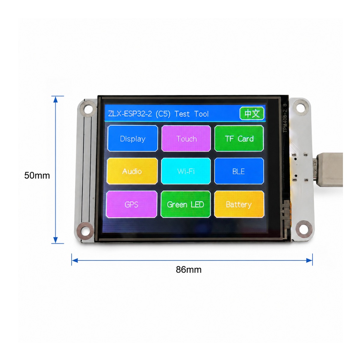
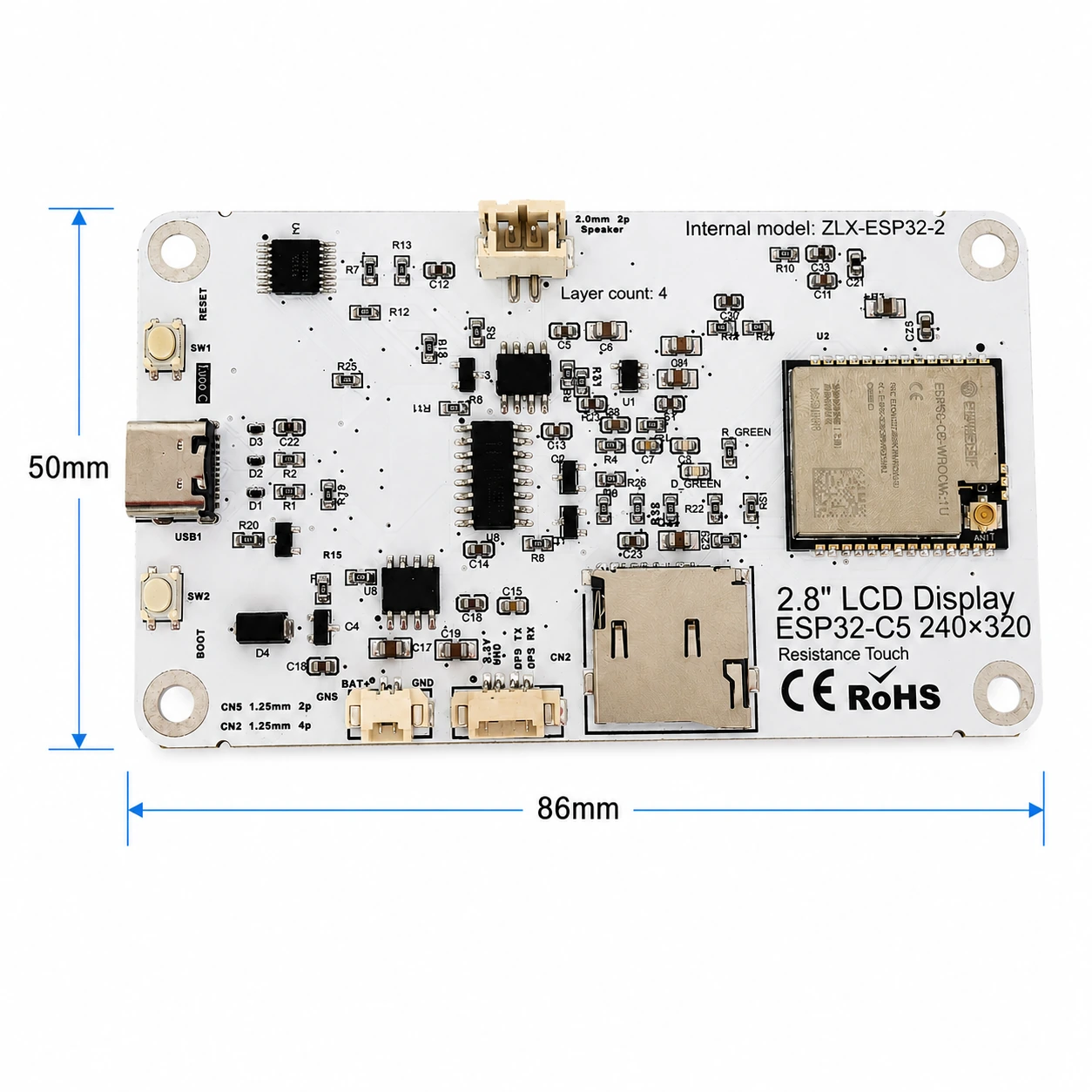
Dimensi keseluruhan papan kira-kira 86 mm × 50 mm. Gambar depan dan belakang berikut digunakan untuk mengidentifikasi layar, antarmuka, dan komponen utama.
The board outline is approximately 86 mm × 50 mm. The images below help identify the display, connectors, and major components.
|
|
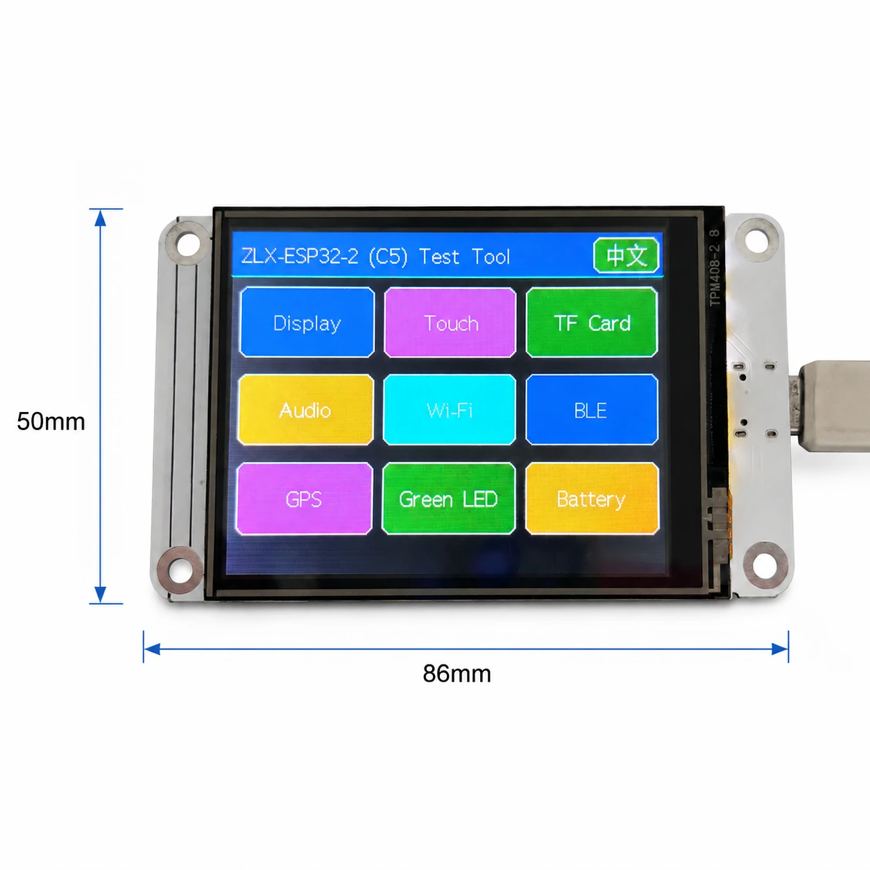
gambar 1 Dimensi depan dan layar / Figure 1 Board front and display-side dimensions
Anotasi antarmuka / Connector Identification
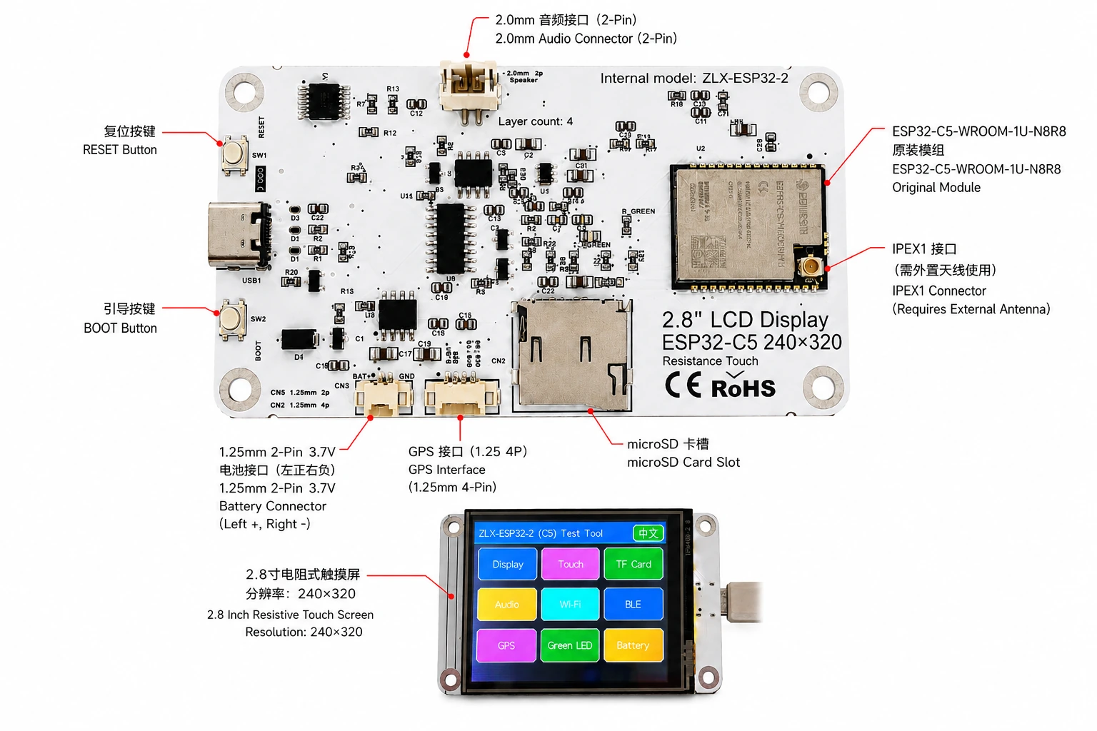
gambar 2 ZLX-ESP32-2 Anotasi antarmuka berbahasa Mandarin dan Inggris / Figure 2 Bilingual connector identification
3. Spesifikasi papan pengembangan / 3. Board Specifications
proyek / Item | Spesifikasi / Specification |
Model papan pengembangan / Board model | ZLX-ESP32-2 |
modul inti / Core module | ESP32-C5-WROOM-1U-N8R8 |
Ukuran papan / Board size | Approx. 86 × 50 mm |
Menampilkan / Display | 2.8-inch TFT LCD, ST7789, 240×320 native resolution |
urutan warna / Color order | BGR initialization |
Tampilkan warna terbalik / Display inversion | OFF / Normal display mode(Jangan nyalakan warna terbalik) |
menyentuh / Touch | Resistive touch / Sentuhan resistif, XPT2046 |
microSD/TF slot kartu / microSD/TF Card Slot | SPI mode; card not included / SPI mode; tidak disertai dengan kartu |
GPS antarmuka / GPS interface | 1.25 mm 4-pin connector; UART signals on GPIO0/GPIO9 |
antarmuka audio / Audio | 2.0 mm 2-pin speaker/audio connector; PWM audio + amplifier enable |
Antarmuka baterai / Battery | 3.7 V 1S, 1.25 mm 2-pin; protected 1000–3000 mAh recommended / satu bagian 3.7 V;saran 1000–3000 mAh Dengan papan pelindung |
antena eksternal / External antenna | IPEX1 connector; required for the WROOM-1U radio path |
tombol / Buttons | RESET, BOOT |
indikasi status / Indicator | Green LED on GPIO26 |
menjelaskan / Note: Resolusi layar asli adalah 240×320;Ketika perangkat lunak diatur ke rotasi layar horizontal, ukuran tampilan logis dapat dinyatakan sebagai 320×240。 / The panel native resolution is 240×320; in landscape rotation, the logical display size may be 320×240.
4. ESP32-C5-WROOM-1U-N8R8 Parameter modul / 4. ESP32-C5-WROOM-1U-N8R8 Module Specifications
Parameter kunci berikut ini didasarkan pada Espressif resmi ESP32-C5-WROOM-1 / WROOM-1U Datasheet v1.2。
The following key parameters are based on Espressif's official ESP32-C5-WROOM-1 / WROOM-1U Datasheet v1.2.
proyek / Item | Spesifikasi / Specification |
Chip bawaan / Embedded SoC | ESP32-C5HR8 |
CPU | 32-bit RISC-V single core, up to 240 MHz |
ROM | 320 KB |
HP SRAM | 384 KB |
LP SRAM | 16 KB |
Flash | 8 MB Quad SPI |
PSRAM | 8 MB Quad SPI |
Wi-Fi | 1T1R, 2.4 GHz + 5 GHz dual-band; IEEE 802.11ax/ac/b/g/n; up to 150 Mbps |
2.4 GHz frekuensi / Frequency | 2412–2484 MHz |
5 GHz frekuensi / Frequency | 5180–5885 MHz (subject to regional regulations) |
Bluetooth | Bluetooth LE; Espressif v1.2 feature list states Bluetooth Core 6.0 certified |
IEEE 802.15.4 | 2.4 GHz OQPSK, 250 Kbps |
Zigbee / Thread | Zigbee 3.0 / Thread 1.4 |
GPIO | Up to 22 GPIOs at module level |
Periferal yang khas / Peripherals | GPIO, SPI, UART, I2C, I2S, RMT, LED PWM, USB Serial/JTAG, MCPWM, GDMA, CAN FD, SDIO slave, ADC, temperature sensor, timers, watchdogs, etc. |
Tegangan kerja modul / Module supply | 3.0–3.6 V, typical 3.3 V |
Kemampuan daya yang direkomendasikan / Recommended supply capability | External supply should be capable of at least 0.6 A for the module |
suhu sekitar / Ambient temperature | -40 to +85 °C |
Ukuran modul / Module size | 18.0 × 21.2 × 3.3 mm |
antena / Antenna | External antenna via connector/module RF path; 50 Ω RF system |
5. Tampilkan dan sentuh / 5. Display and Touch
LCD parameter / LCD Parameters
proyek / Item | Spesifikasi / Specification |
ukuran / Size | 2.8 inch |
menyetir IC / Driver IC | ST7789 |
resolusi asli / Native resolution | 240 × 320 |
Resolusi logis layar horizontal / Landscape logical resolution | 320 × 240 (depending on rotation setting) |
urutan warna / Color order | BGR |
warna terbalik / Inversion | Disabled / OFF; normal display mode |
SPI jam / SCK | GPIO6 |
SPI MOSI | GPIO7 |
SPI MISO | GPIO2 (shared with TF card; used if required by library/readback) |
LCD CS | GPIO10 |
LCD Backlight / lampu latar | GPIO13 |
LCD DC / RS | GPIO14 |
Parameter sentuh / Touch Parameters
Jenis sentuhan:4 Sentuhan Resistif Kawat; Pengendali:XPT2046。 / Touch type: 4-wire resistive; controller: XPT2046.
DOUT=GPIO3,SCK=GPIO4,DIN=GPIO5。 / DOUT=GPIO3, SCK=GPIO4, DIN=GPIO5.
CS=GPIO23,IRQ=GPIO25。 / CS=GPIO23, IRQ=GPIO25.
Sentuh untuk menggunakan perangkat lunak mandiri SPI;Proses alat deteksi ditandai tidak memerlukan kalibrasi. / Touch uses an independent software SPI; the supplied test flow is marked as requiring no calibration.
6. GPIO pemetaan / 6. GPIO Mapping
Pemetaan berikut berasal dari versi pelanggan yang disediakan bersama papan GPIO Spreadsheet dan diperiksa berdasarkan skema. Penggunaan periferal di dalam pesawat 19 Biasa saja GPIO;TX0=GPIO11、RX0=GPIO12 Juga digunakan untuk UART0;N8R8 dari GPIO15 selimut PSRAM oleh karena itu ditempati 21 tersedia GPIO Semua ditugaskan;EN Tidak dihitung sebagai pekerjaan GPIO。
The mapping below is based on the supplied GPIO spreadsheet and cross-checked against the schematic. Board peripherals use 19 GPIOs; TX0=GPIO11 and RX0=GPIO12 are additionally used by UART0; GPIO15 is reserved by PSRAM on N8R8, so all 21 usable GPIOs are allocated; EN is not a GPIO.
GPIO | Signal | definisi / Definition | arah / Direction | Fungsi / Function | menjelaskan / Notes |
0 | GPSTX | GPS port serial TX / GPS UART TX | Input / Masukkan | GPS test / GPStes | GPS module TX → ESP32-C5 |
1 | BAT_ADC | Deteksi tegangan baterai / Battery voltage sensing | Input/ADC | Battery test | 100k/100k divider; ADC × 2 ≈ battery voltage |
2 | SD_MISO | TF DAT0 / LCD MISO membagikan / Shared | Input | TF card test | Shared SPI MISO |
3 | RTP_DOUT | XPT2046 DOUT | Input | Touch test | Touch controller data output |
4 | RTP_SCK | XPT2046 SCK | Output | Touch test | Independent software SPI |
5 | RTP_DIN | XPT2046 DIN | Output | Touch test | Independent software SPI |
6 | LCD_SCK | LCD SCK / TF SCK membagikan / Shared | Output | LCD/TF test | Shared SPI clock |
7 | LCD_MOSI | LCD MOSI / TF CMD(MOSI) membagikan / Shared | Output | LCD/TF test | Shared SPI MOSI |
8 | AUDIOPWM | Frekuensi Audio PWM / Audio PWM | Output | Audio test | Audio output control |
9 | GPSRX | GPS port serial RX / GPS UART RX | Output | GPS test | ESP32-C5 TX → GPS module RX |
10 | LCDCS | ST7789 CS | Output | Display test | LCD chip select |
13 | LCDBL | LCD lampu latar / LCD backlight | Output | Display test | Backlight control |
14 | LCD_RS/DC | ST7789 DC | Output | Display test | Data/command select |
23 | RTPCS | XPT2046 CS | Output | Touch test | Touch chip select |
24 | AMP_EN | Penguat diaktifkan / Amplifier enable | Output | Audio test | High-level enable per supplied mapping; verify actual hardware revision |
25 | RTPIRQ | XPT2046 IRQ | Input | Touch test | Touch interrupt |
26 | GREENLED | hijau LED / Green LED | Output | LED test | HIGH = ON, LOW = OFF |
27 | SDCS | TF DAT3 / CS | Output | TF card test | TF card SPI chip select |
28 | BOOTAUTO | BOOT / kontrol start otomatis / auto-start control | Input/Control | Factory restore | BOOT input / factory-restore logic |
Sinyal sistem dan port serial / System and UART Signals
Sinyal / Signal | menggunakan / Purpose | Komentar / Note |
RESET_AUTO / EN | ESP32 reset / enable / ESP32 Setel ulang dan aktifkan | System enable/reset; not a GPIO / Pengaktifan sistem/Reset, bukan milik GPIO |
UART0_TX / TX0 / GPIO11 | UART0 transmit / UART0 Pengiriman port serial | Used; excluded from the 19 peripheral GPIO count / Digunakan; tidak dihitung di atas 19 periferal GPIO |
UART0_RX / RX0 / GPIO12 | UART0 receive / UART0 Penerimaan port serial | Used; excluded from the 19 peripheral GPIO count / Digunakan; tidak dihitung di atas 19 periferal GPIO |
7. Antarmuka dan instruksi berbagi bus / 7. Interface and Bus Sharing
proyek / Item | GPIO | menjelaskan / Description |
LCD + TF SPI membagikan / Shared SPI | GPIO6 / GPIO7 / GPIO2 | SCK, MOSI, MISO shared; devices separated by independent CS / Jam dan jalur data bersama, gunakan independen CS Bedakan antar perangkat |
LCD CS | GPIO10 | LCD_CS |
TF card CS | GPIO27 | SD_CS / DAT3 |
XPT2046 touch | GPIO3 / 4 / 5 / 23 / 25 | DOUT / SCK / DIN / CS / IRQ |
GPS UART | GPIO0 / GPIO9 | GPSTX / GPSRX; GPIO0 receives GPS TX, GPIO9 drives GPS RX |
Battery ADC | GPIO1 | BAT_ADC; 100k/100k divider; C20 100 nF filtering |
Green LED | GPIO26 | HIGH ON, LOW OFF |
Audio | GPIO8 / GPIO24 | AUDIOPWM / AMP_EN |
LCD control | GPIO13 / GPIO14 | Backlight / DC |
SPI Berbagi pertimbangan / SPI Sharing Notes
LCD Dan TF Berbagi kartu GPIO6(SCK)、GPIO7(MOSI)、GPIO2(MISO), tetapi menggunakan masing-masing GPIO10(LCD_CS) Dan GPIO27(SD_CS)。 / LCD and TF card share GPIO6 (SCK), GPIO7 (MOSI), and GPIO2 (MISO), but use GPIO10 (LCD_CS) and GPIO27 (SD_CS) respectively.
Hanya aktifkan perangkat target secara bersamaan CS, untuk menghindari konflik bus yang disebabkan oleh beberapa perangkat yang dipilih secara bersamaan. / Assert only the target device CS at a time to avoid bus contention.
menyentuh XPT2046 Gunakan perangkat lunak mandiri SPI, bukan dengan LCD/TF Yang mulia SPI jam dan MOSI dibagikan. / The XPT2046 touch controller uses an independent software SPI and does not share the main LCD/TF SCK/MOSI signals.
8. Korespondensi fungsi deteksi / 8. Functional Test Mapping
item tes / Test | GPIO | Konten deteksi / What is tested | hasil/menjelaskan / Result/Note |
tes layar / Display | GPIO6, 7, 10, 13, 14, 2 | ST7789 display, 240×320 native / 320×240 landscape; BGR; backlight | Normal / Abnormal |
tes sentuh / Touch | GPIO3, 4, 5, 23, 25 | XPT2046 touch response | Test flow: no calibration |
TF tes kartu / TF card | GPIO2, 6, 7, 27 | SPI init, read/write/format | Shares SPI with LCD |
tes audio / Audio | GPIO8, 24 | PWM audio and amplifier enable | Continuous playback depends on firmware |
Wi-Fi tes / Wi-Fi | Internal RF | 2.4 GHz / 5 GHz scan | No listed GPIO occupied |
BLE tes / BLE | Internal RF | BLE scan | No listed GPIO occupied |
GPS tes / GPS | GPIO0, 9 | GPS UART data | GPSTX / GPSRX |
LED tes / LED | GPIO26 | Green LED | HIGH on / LOW off |
Pengujian baterai / Battery | GPIO1 | ADC measures divided battery voltage | Voltage estimate, not a coulomb counter |
BOOT Reset pabrik / Factory restore | GPIO28 | BOOT input / restore logic | Behavior is defined by firmware |
9. Pertimbangan antarmuka dan kelistrikan / 9. Connector and Electrical Notes
Antarmuka baterai / Battery Connector
Papan pengembangan disediakan 1.25 mm 2-Pin 3.7 V Antarmuka baterai tunggal. Menurut arah tampilan diagram yang ditandai, sisi kiri adalah elektroda positif (+), sisi kanan adalah kutub negatif (-). Jika daya baterai diperlukan, disarankan untuk menggunakan kapasitas 1000–3000 mAh, satu bagian dengan papan pelindung (sirkuit pelindung) 3.7 V ion litium/Baterai polimer litium, dan konfirmasikan spesifikasi antarmuka serta kutub positif dan negatif sebelum menghubungkan. Koneksi terbalik dapat merusak papan pengembangan.
The board provides a 1.25 mm 2-pin connector for a single-cell 3.7 V battery. In the orientation shown in the labeled image, the left pin is positive (+) and the right pin is negative (-). For battery-powered operation, use a protected single-cell 3.7 V Li-ion/LiPo battery; 1000–3000 mAh is recommended. Verify connector type and polarity before connection. Reverse polarity may damage the board.
GPIO1 lulus 100 kΩ / 100 kΩ Jaringan pembagi tegangan mendeteksi tegangan baterai, sehingga dalam keadaan ideal, tegangan baterai sebenarnya adalah kira-kira ADC tegangan pin 2 kali. Fungsi ini hanya untuk estimasi tegangan, bukan pengukur coulomb bahan bakar.
GPIO1 senses battery voltage through a 100 kΩ / 100 kΩ divider, so ideally the battery voltage is approximately 2× the ADC pin voltage. This is a voltage estimate only and is not a fuel-gauge/coulomb-counter measurement.
GPS antarmuka / GPS Interface
GPS menggunakan GPIO0 Dan GPIO9 sebagai UART Sinyal.GPIO0(GPSTX bernama) sebagai masukan dalam definisi papan ini, sambungkan GPS modul TX;GPIO9(GPSRX bernama) sebagai output, sambungkan GPS modul RX。1.25 mm 4-Pin Silakan merujuk ke versi perangkat keras yang sesuai untuk pin daya dan urutan pin konektor yang sebenarnya./Diagram skematik akan berlaku.
GPS uses GPIO0 and GPIO9 as UART signals. In this board mapping, GPIO0 (named GPSTX) is an input connected to the GPS module TX, while GPIO9 (named GPSRX) is an output connected to the GPS module RX. For the 1.25 mm 4-pin connector power pins and exact physical pin order, follow the silkscreen/schematic of the specific hardware revision.
antena eksternal / External Antenna
ESP32-C5-WROOM-1U Ini adalah versi antena eksternal. papan IPEX1 Antarmuka perlu dihubungkan 2.4/5 GHz Pencocokan pita frekuensi dan impedansinya adalah 50 Ω antena. Jangan melakukan transmisi dengan daya tinggi dalam waktu lama tanpa antena yang sesuai tersambung.
ESP32-C5-WROOM-1U is the external-antenna variant. Connect a suitable 2.4/5 GHz, 50-ohm antenna to the IPEX1 connector. Avoid prolonged high-power transmission without a proper antenna attached.
antarmuka audio / Audio Connector
Output audio disediakan oleh GPIO8(AUDIOPWM)menghasilkan PWM Sinyal,GPIO24(AMP_EN) mengontrol pengaktifan penguat daya; bagian atas papan adalah 2.0 mm 2-Pin Frekuensi Audio/Antarmuka pengeras suara. Silakan lihat kemampuan rangkaian penguat daya sebenarnya untuk pengaturan beban dan volume yang berbeda.
Audio output uses GPIO8 (AUDIOPWM) for the PWM signal and GPIO24 (AMP_EN) for amplifier enable. The top connector is a 2.0 mm 2-pin audio/speaker connector. Use loads and volume settings within the capability of the actual amplifier circuit.
10. Saran pengembangan dan inisialisasi perangkat lunak / 10. Software Development and Initialization Notes
Tampilkan pilihan driver ST7789, resolusi asli disetel ke 240×320;Layar horizontal dapat diputar 320×240。 / Select ST7789 as the display driver and use 240×320 as the native resolution; set rotation for 320×240 landscape as supported by your graphics library.
Urutan warna yang digunakan BGR;Jangan aktifkan tampilan warna terbalik (INVON)。 / Use BGR color order; do not enable display inversion (INVON).
LCD/TF membagikan SPI kapan, dikelola secara terpisah setelah inisialisasi LCD_CS(GPIO10) Dan SD_CS(GPIO27)。 / When LCD and TF share SPI, manage LCD_CS (GPIO10) and SD_CS (GPIO27) independently after initialization.
XPT2046 menggunakan GPIO3/4/5/23/25 perangkat lunak independen SPI。 / XPT2046 uses an independent software SPI on GPIO3/4/5/23/25.
Saat membaca tegangan baterai, GPIO1 dari ADC Hasil sekitar. 2:1 Konversi rasio tekanan parsial, dikombinasikan dengan ADC Kalibrasi meningkatkan akurasi. / For battery voltage, convert the GPIO1 ADC reading using the approximately 2:1 divider ratio and apply ADC calibration for better accuracy.
Wi-Fi 5 GHz Saluran yang tersedia dan daya pancar bervariasi tergantung negara/Pembatasan peraturan regional. / Available 5 GHz Wi-Fi channels and transmit power depend on local regulations.
BOOT/Logika pemulihan pabrik ditentukan oleh firmware; hindari kesalahan pemicuan selama pengoperasian dan menyebabkan konfigurasi dihapus. / BOOT/factory-restore behavior is firmware-defined; avoid unintended activation that may clear settings.
Urutan inisialisasi yang disarankan / Suggested Initialization Sequence
1. Inisialisasi sistem dan port serial setelah catu daya stabil.
After power is stable, initialize the system and debug UART.
2. inisialisasi LCD SPI,mendirikan ST7789、BGR, matikan warna terbalik, lalu nyalakan lampu latar.
Initialize LCD SPI; configure ST7789, BGR, inversion off, then enable backlight.
3. inisialisasi XPT2046 menyentuh.
Initialize XPT2046 touch.
4. Jika Anda perlu menggunakan fungsi penyimpanan, silakan masukkan kompatibel yang telah disiapkan pengguna microSD/TF kartu, inisialisasi ulang, dan pastikan LCD_CS Dan SD_CS Statusnya benar.
If removable storage is required, insert a compatible user-supplied microSD/TF card, then initialize it and ensure correct LCD_CS/SD_CS states.
5. Inisialisasi sesuai permintaan GPS,audio,LED,Baterai ADC。
Initialize GPS, audio, LED, and battery ADC as needed.
6. Terakhir diaktifkan Wi-Fi/BLE/802.15.4 Kemampuan nirkabel.
Enable Wi-Fi/BLE/802.15.4 radio functions as required.
11. Memecahkan masalah umum / 11. Troubleshooting
pertanyaan / Issue | English | Metode pengobatan / Solution | Solution (EN) |
Layar putih/layar hitam | Blank/black display | meneliti GPIO6/7/10/13/14、ST7789 pemilihan pengemudi,BGR pengaturan, lampu latar GPIO13 Dan apakah warna kebalikannya diaktifkan secara tidak sengaja. | Check GPIO6/7/10/13/14, ST7789 driver selection, BGR setting, backlight GPIO13, and whether inversion was accidentally enabled. |
warna salah | Incorrect colors | Konfirmasikan bahwa urutan warna perpustakaan grafis adalah BGR。 | Confirm the graphics library is configured for BGR color order. |
Tidak ada respons terhadap sentuhan | No touch response | meneliti GPIO3/4/5/23/25 Dan XPT2046 inisialisasi. | Check GPIO3/4/5/23/25 and XPT2046 initialization. |
TF Inisialisasi kartu gagal | TF card init fails | meneliti LCD/TF membagikan SPI dari SCK/MOSI/MISO,maupun SD_CS(GPIO27) Dan LCD_CS(GPIO10) Apakah ada konflik. | Check shared SPI SCK/MOSI/MISO and make sure SD_CS (GPIO27) and LCD_CS (GPIO10) are not asserted simultaneously. |
Wi-Fi Sinyal lemah atau tidak dapat dipindai | Weak/no Wi-Fi | mengonfirmasi IPEX1 Antena eksternal terhubung dan didukung menggunakan 2.4/5 GHz antena yang cocok. | Confirm the IPEX1 external antenna is connected and suitable for 2.4/5 GHz. |
Pembacaan tegangan baterai sekitar setengah sebenarnya | Battery reading is about half | GPIO1 Ujung depannya adalah 100k/100k Tekanan parsial perlu dikalikan dengan kira-kira saat mengkonversi 2。 | GPIO1 uses a 100k/100k divider; multiply the ADC-side voltage by approximately 2. |
GPS Tidak ada data | No GPS data | mengonfirmasi GPIO0 menangkap GPS TX、GPIO9 menangkap GPS RX, dan periksa baud rate dan catu daya. | Confirm GPIO0 receives GPS TX, GPIO9 drives GPS RX, and verify baud rate and power. |
12. Pengunduhan data dan dukungan teknis / 12. Downloads and Technical Support
ZLX-ESP32-2 Harap berikan akses prioritas ke firmware, file, informasi tindak lanjut, dan dukungan terkait. ZLX ESP32 Pusat Dukungan Pembuat Dewan Pengembangan. Harap konfirmasi apa yang tercantum pada halaman sebelum menginstal firmware. PCB Modelnya sama persis dengan papan yang ada di tangan.
For ZLX-ESP32-2 firmware, files, future documentation, and related support, use the ZLX ESP32 development-board support center. Before flashing firmware, confirm the PCB model shown on the website exactly matches your hardware.
Pengunduhan data / Downloads: https://www.zlxchina.xyz/
Espressif module datasheet / Spesifikasi Modul Espressif: ESP32-C5-WROOM-1 / WROOM-1U Datasheet
Referensi / References
ZLX ESP32 Pusat Dukungan Pembuat Dewan Pengembangan / ZLX ESP32 Development Board Support Center — https://www.zlxchina.xyz/
Espressif ESP32-C5-WROOM-1 & WROOM-1U Datasheet v1.2 (2026-08-12) / Espressif ESP32-C5-WROOM-1 & WROOM-1U Datasheet v1.2 (2026-08-12) — https://espressif.com/documentation/esp32-c5-wroom-1_wroom-1u_datasheet_en.pdf
13. Tindakan pencegahan penggunaan dan keamanan / 13. Safety and Handling
Kutub positif dan negatif harus dikonfirmasi sebelum menghubungkan baterai, dan koneksi terbalik dilarang. / Verify battery polarity before connection; never reverse the battery connector.
Pasang dan cabut IPEX Pertahankan gaya vertikal saat menyambungkan antena untuk menghindari pencungkilan lateral yang dapat menyebabkan basis RF terlepas. / When mating/unmating the IPEX connector, apply force vertically and avoid sideways prying that may damage the RF socket.
Saat menggunakan papan kosong pada papan pengembangan, perhatikan perlindungan elektrostatis untuk menghindari korsleting yang disebabkan oleh benda logam. / Use ESD precautions with the bare board and prevent metal objects from causing shorts.
5 GHz Pita frekuensi, saluran, dan daya nirkabel harus mematuhi peraturan di wilayah penggunaan. / 5 GHz radio band, channels, and transmit power must comply with local regulations.
TF Kartu,GPSHarap ikuti versi perangkat keras sebenarnya untuk mengetahui kemampuan catu daya dan level periferal seperti audio dan video. Jangan menghubungi kami tanpa konfirmasi. IO pin diterapkan di atas 3.3 V tingkat. / For TF, GPS, audio, and other peripherals, follow the actual hardware revision for supply and logic levels. Do not apply logic levels above 3.3 V to IO pins unless explicitly verified.
14. Catatan versi dokumen / 14. Document Revision History
Versi / Rev. | tanggal / Date | isi / Description | sumber / Basis |
V1.1 | 2026-08-25 | Revisi:microSD/TF, baterai dan GPIO menjelaskan. | Hefei Zhiluxing Information Technology Co., Ltd. |
— End / Menyelesaikan -