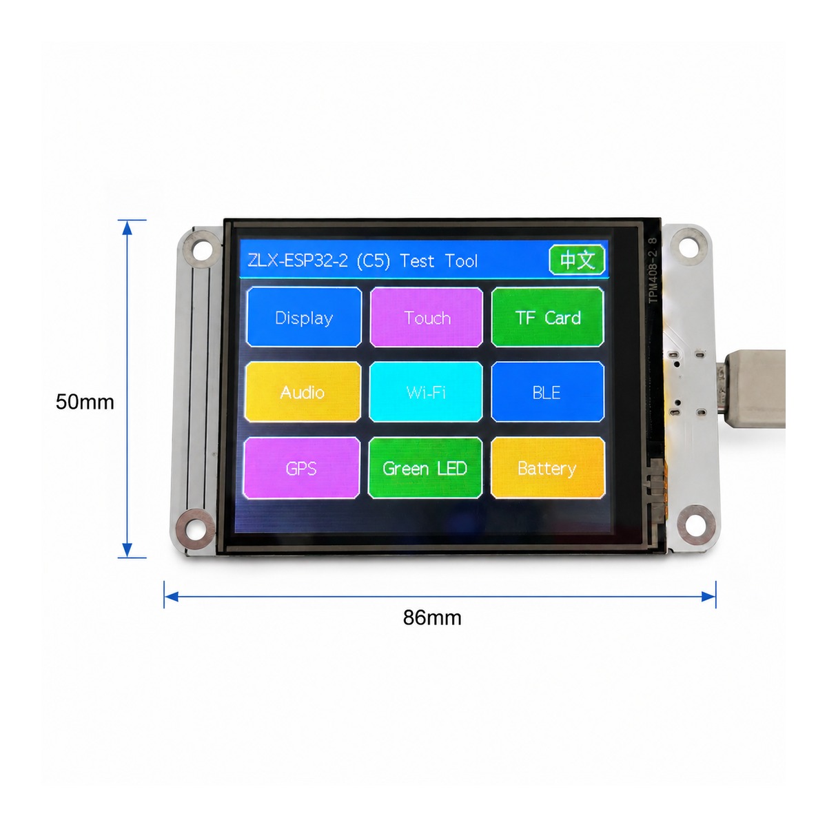
ZLX-ESP32-2
ESP32-C5 2.8-inch Touch Display Development Board
Manuale utente cinese e inglese / Bilingual User Manual
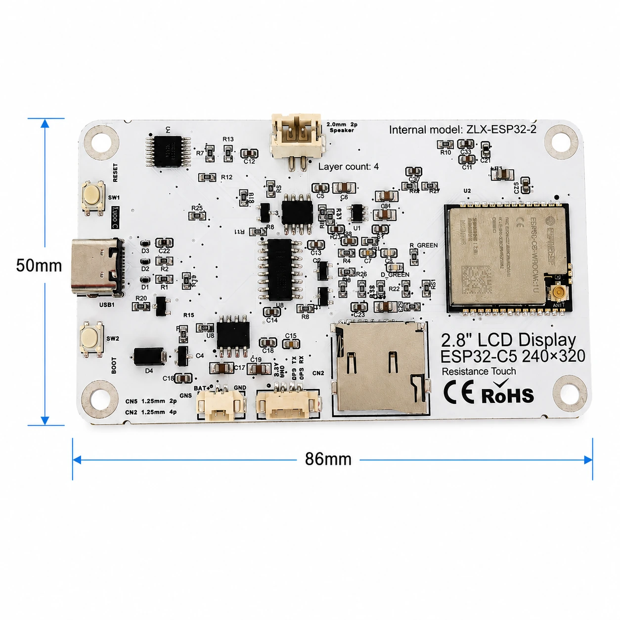
Model / Modello: ZLX-ESP32-2
Module / modulo: ESP32-C5-WROOM-1U-N8R8
Document Version / Versione del documento: V1.1 | 2026-08-25
1. Overview / 1. Product Overview
ZLX-ESP32-2 è un prodotto basato su ESP32-C5-WROOM-1U-N8R8 Modulare 2.8 Scheda di sviluppo touch screen resistivo da pollici con colore integrato LCD、XPT2046 tocco,microSD/TF Slot per scheda (solo slot per scheda, non incluso microSD/TF carta),GPS Interfaccia, uscita audio, rilevamento tensione batteria, verde LED、BOOT/RESET Pulsante e interfaccia antenna esterna. Adatto Wi-Fi 6、Bluetooth LE、Zigbee/Thread, interfaccia uomo-macchina, registrazione dati e sviluppo di applicazioni Internet of Things.
ZLX-ESP32-2 is a 2.8-inch resistive-touch development board based on the ESP32-C5-WROOM-1U-N8R8 module. It integrates a color LCD, XPT2046 touch controller, a microSD/TF card slot (slot only; no microSD/TF card is included), GPS interface, audio output, battery-voltage sensing, green LED, BOOT/RESET buttons, and an external-antenna connector. It is suitable for Wi-Fi 6, Bluetooth LE, Zigbee/Thread, HMI, data logging, and IoT development.
Caratteristiche principali: / Key Features
ESP32-C5 32 Morso RISC-V Processore single-core, fino a 240 MHz / ESP32-C5 32-bit RISC-V single-core CPU, up to 240 MHz
ESP32-C5-WROOM-1U-N8R8:8 MB Flash + 8 MB PSRAM(Risorse integrate nel modulo, no microSD/TF carta) / ESP32-C5-WROOM-1U-N8R8: 8 MB Flash + 8 MB PSRAM (onboard module memory, not a microSD/TF card)
2.4 GHz + 5 GHz Doppia banda Wi-Fi 6(802.11ax) / 2.4 GHz + 5 GHz dual-band Wi-Fi 6 (802.11ax)
Bluetooth LE、IEEE 802.15.4、Zigbee 3.0、Thread 1.4 / Bluetooth LE, IEEE 802.15.4, Zigbee 3.0, Thread 1.4
2.8 pollice 240×320 LCD,ST7789 guidare,BGR Inizializzazione, disabilita il colore inverso / 2.8-inch 240×320 LCD, ST7789 driver, BGR initialization, display inversion disabled
XPT2046 Controller touch resistivo / XPT2046 resistive touch controller
LCD E TF Condivisione delle carte SPI autobus, indipendente CS;Toccare per utilizzare il software autonomo SPI / LCD and TF card share SPI with separate CS; touch uses an independent software SPI
Dimensioni della tavola ca. 86 mm × 50 mm / Board size approx. 86 mm × 50 mm
IPEX1 Interfaccia antenna esterna; l'antenna esterna deve essere collegata correttamente prima di utilizzare la funzione wireless / IPEX1 external antenna connector; connect a suitable external antenna before radio use
Oggetti applicabili / Intended Users
Adatto a sviluppatori embedded, sviluppatori IoT, produttori, esperimenti didattici e progettazione di prototipi di prodotto.
For embedded developers, IoT developers, makers, education/lab use, and product prototyping.
2. Aspetto e dimensioni / 2. Appearance and Dimensions
Le dimensioni complessive della tavola sono approssimative 86 mm × 50 mm. Le seguenti immagini fronte e retro vengono utilizzate per identificare lo schermo, le interfacce e i componenti principali.
The board outline is approximately 86 mm × 50 mm. The images below help identify the display, connectors, and major components.
|
|
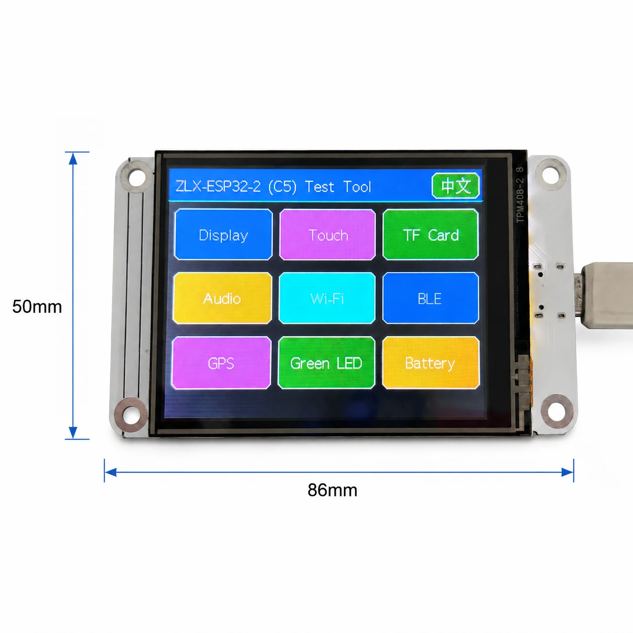
immagine 1 Dimensioni frontale e schermo / Figure 1 Board front and display-side dimensions
Callout interfaccia / Connector Identification
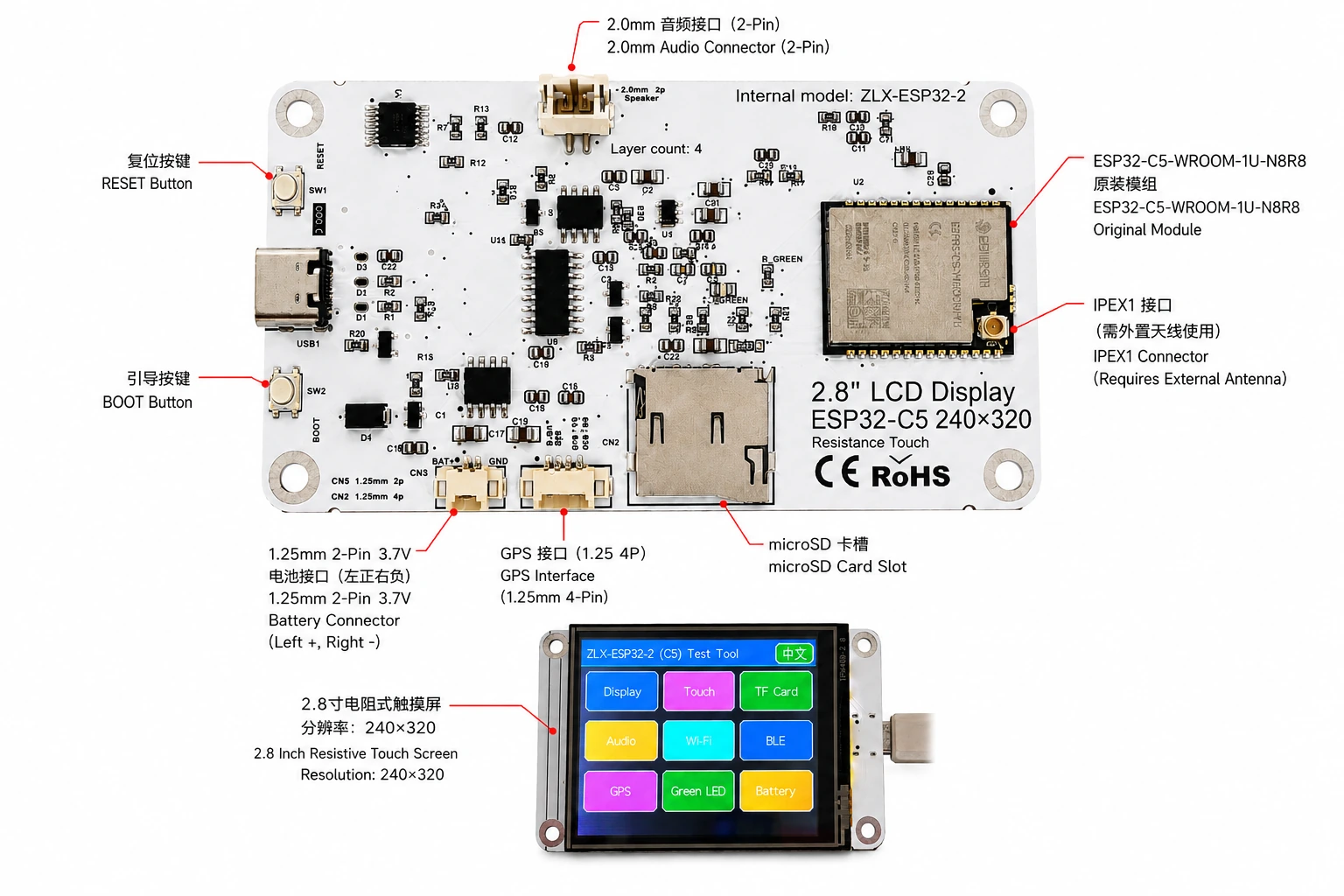
immagine 2 ZLX-ESP32-2 Annotazioni sull'interfaccia cinese e inglese / Figure 2 Bilingual connector identification
3. Specifiche della scheda di sviluppo / 3. Board Specifications
progetto / Item | FORMATO / Specification |
Modello della scheda di sviluppo / Board model | ZLX-ESP32-2 |
modulo principale / Core module | ESP32-C5-WROOM-1U-N8R8 |
Dimensioni della tavola / Board size | Approx. 86 × 50 mm |
Display / Display | 2.8-inch TFT LCD, ST7789, 240×320 native resolution |
Ordine dei colori / Color order | BGR initialization |
Mostra il colore inverso / Display inversion | OFF / Normal display mode(Non attivare il colore inverso) |
- Alla nonna. / Touch | Resistive touch / Tocco resistivo, XPT2046 |
microSD/TF slot per schede / microSD/TF Card Slot | SPI mode; card not included / SPI modalità; non viene fornito con la carta |
GPS interfaccia / GPS interface | 1.25 mm 4-pin connector; UART signals on GPIO0/GPIO9 |
interfaccia audio / Audio | 2.0 mm 2-pin speaker/audio connector; PWM audio + amplifier enable |
Interfaccia batteria / Battery | 3.7 V 1S, 1.25 mm 2-pin; protected 1000–3000 mAh recommended / sezione unica 3.7 V;suggerimento 1000–3000 mAh Con pannello protettivo |
Antenna esterna / External antenna | IPEX1 connector; required for the WROOM-1U radio path |
pulsante / Buttons | RESET, BOOT |
indicazione dello stato / Indicator | Green LED on GPIO26 |
Description / Note: La risoluzione nativa dello schermo è 240×320;Quando il software è impostato sulla rotazione orizzontale dello schermo, la dimensione logica del display può essere espressa come 320×240。 / The panel native resolution is 240×320; in landscape rotation, the logical display size may be 320×240.
4. ESP32-C5-WROOM-1U-N8R8 Parametri del modulo / 4. ESP32-C5-WROOM-1U-N8R8 Module Specifications
Si basano sui seguenti parametri chiave Espressif ufficiale ESP32-C5-WROOM-1 / WROOM-1U Datasheet v1.2。
The following key parameters are based on Espressif's official ESP32-C5-WROOM-1 / WROOM-1U Datasheet v1.2.
progetto / Item | FORMATO / Specification |
Chip integrato / Embedded SoC | ESP32-C5HR8 |
CPU | 32-bit RISC-V single core, up to 240 MHz |
ROM | 320 KB |
HP SRAM | 384 KB |
LP SRAM | 16 KB |
Flash | 8 MB Quad SPI |
PSRAM | 8 MB Quad SPI |
Wi-Fi | 1T1R, 2.4 GHz + 5 GHz dual-band; IEEE 802.11ax/ac/b/g/n; up to 150 Mbps |
2.4 GHz frequenza / Frequency | 2412–2484 MHz |
5 GHz frequenza / Frequency | 5180–5885 MHz (subject to regional regulations) |
Bluetooth | Bluetooth LE; Espressif v1.2 feature list states Bluetooth Core 6.0 certified |
IEEE 802.15.4 | 2.4 GHz OQPSK, 250 Kbps |
Zigbee / Thread | Zigbee 3.0 / Thread 1.4 |
GPIO | Up to 22 GPIOs at module level |
Periferiche tipiche / Peripherals | GPIO, SPI, UART, I2C, I2S, RMT, LED PWM, USB Serial/JTAG, MCPWM, GDMA, CAN FD, SDIO slave, ADC, temperature sensor, timers, watchdogs, etc. |
Tensione di lavoro del modulo / Module supply | 3.0–3.6 V, typical 3.3 V |
Capacità di alimentazione consigliate / Recommended supply capability | External supply should be capable of at least 0.6 A for the module |
temperatura ambiente / Ambient temperature | -40 to +85 °C |
Dimensioni del modulo / Module size | 18.0 × 21.2 × 3.3 mm |
Antenna / Antenna | External antenna via connector/module RF path; 50 Ω RF system |
5. Visualizza e tocca / 5. Display and Touch
LCD PARAMETRI / LCD Parameters
progetto / Item | FORMATO / Specification |
misurare / Size | 2.8 inch |
guidare IC / Driver IC | ST7789 |
risoluzione nativa / Native resolution | 240 × 320 |
Risoluzione logica dello schermo orizzontale / Landscape logical resolution | 320 × 240 (depending on rotation setting) |
Ordine dei colori / Color order | BGR |
colore inverso / Inversion | Disabled / OFF; normal display mode |
SPI Orologio / SCK | GPIO6 |
SPI MOSI | GPIO7 |
SPI MISO | GPIO2 (shared with TF card; used if required by library/readback) |
LCD CS | GPIO10 |
LCD Backlight / retroilluminazione | GPIO13 |
LCD DC / RS | GPIO14 |
Toccare i parametri / Touch Parameters
Tipo di tocco:4 Tocco resistivo del filo; Controllore:XPT2046。 / Touch type: 4-wire resistive; controller: XPT2046.
DOUT=GPIO3,SCK=GPIO4,DIN=GPIO5。 / DOUT=GPIO3, SCK=GPIO4, DIN=GPIO5.
CS=GPIO23,IRQ=GPIO25。 / CS=GPIO23, IRQ=GPIO25.
Toccare per utilizzare il software autonomo SPI;Il processo dello strumento di rilevamento è contrassegnato come non richiede calibrazione. / Touch uses an independent software SPI; the supplied test flow is marked as requiring no calibration.
6. GPIO mappatura / 6. GPIO Mapping
Le seguenti mappature provengono dalla versione cliente fornita con la scheda GPIO Foglio di calcolo e controllo rispetto allo schema. Utilizzo delle periferiche integrate 19 Un ordinario GPIO;TX0=GPIO11、RX0=GPIO12 Utilizzato anche per UART0;N8R8 Di GPIO15 trapunta PSRAM occupato, quindi 21 disponibile GPIO Tutti assegnati;EN Non conteggiato come lavoro GPIO。
The mapping below is based on the supplied GPIO spreadsheet and cross-checked against the schematic. Board peripherals use 19 GPIOs; TX0=GPIO11 and RX0=GPIO12 are additionally used by UART0; GPIO15 is reserved by PSRAM on N8R8, so all 21 usable GPIOs are allocated; EN is not a GPIO.
GPIO | Signal | definizione / Definition | Direzione / Direction | Funzione / Function | Description / Notes |
0 | GPSTX | GPS porta seriale TX / GPS UART TX | Input / entrare | GPS test / GPStest | GPS module TX → ESP32-C5 |
1 | BAT_ADC | Rilevamento della tensione della batteria / Battery voltage sensing | Input/ADC | Battery test | 100k/100k divider; ADC × 2 ≈ battery voltage |
2 | SD_MISO | TF DAT0 / LCD MISO condividere / Shared | Input | TF card test | Shared SPI MISO |
3 | RTP_DOUT | XPT2046 DOUT | Input | Touch test | Touch controller data output |
4 | RTP_SCK | XPT2046 SCK | Output | Touch test | Independent software SPI |
5 | RTP_DIN | XPT2046 DIN | Output | Touch test | Independent software SPI |
6 | LCD_SCK | LCD SCK / TF SCK condividere / Shared | Output | LCD/TF test | Shared SPI clock |
7 | LCD_MOSI | LCD MOSI / TF CMD(MOSI) condividere / Shared | Output | LCD/TF test | Shared SPI MOSI |
8 | AUDIOPWM | Audio PWM / Audio PWM | Output | Audio test | Audio output control |
9 | GPSRX | GPS porta seriale RX / GPS UART RX | Output | GPS test | ESP32-C5 TX → GPS module RX |
10 | LCDCS | ST7789 CS | Output | Display test | LCD chip select |
13 | LCDBL | LCD retroilluminazione / LCD backlight | Output | Display test | Backlight control |
14 | LCD_RS/DC | ST7789 DC | Output | Display test | Data/command select |
23 | RTPCS | XPT2046 CS | Output | Touch test | Touch chip select |
24 | AMP_EN | Amplificatore abilitato / Amplifier enable | Output | Audio test | High-level enable per supplied mapping; verify actual hardware revision |
25 | RTPIRQ | XPT2046 IRQ | Input | Touch test | Touch interrupt |
26 | GREENLED | verde LED / Green LED | Output | LED test | HIGH = ON, LOW = OFF |
27 | SDCS | TF DAT3 / CS | Output | TF card test | TF card SPI chip select |
28 | BOOTAUTO | BOOT / controllo di avvio automatico / auto-start control | Input/Control | Factory restore | BOOT input / factory-restore logic |
Segnali di sistema e porta seriale / System and UART Signals
Segnaletica / Signal | utilizzo / Purpose | Osservazione / Note |
RESET_AUTO / EN | ESP32 reset / enable / ESP32 Reimposta e attiva | System enable/reset; not a GPIO / Abilitazione del sistema/Ripristina, non appartiene a GPIO |
UART0_TX / TX0 / GPIO11 | UART0 transmit / UART0 Invio tramite porta seriale | Used; excluded from the 19 peripheral GPIO count / Usato; non conteggiato in quanto sopra 19 periferiche GPIO |
UART0_RX / RX0 / GPIO12 | UART0 receive / UART0 Ricezione della porta seriale | Used; excluded from the 19 peripheral GPIO count / Usato; non conteggiato in quanto sopra 19 periferiche GPIO |
7. Istruzioni per la condivisione dell'interfaccia e del bus / 7. Interface and Bus Sharing
progetto / Item | GPIO | Description / Description |
LCD + TF SPI condividere / Shared SPI | GPIO6 / GPIO7 / GPIO2 | SCK, MOSI, MISO shared; devices separated by independent CS / Orologio e linee dati condivise, utilizzo indipendente CS Distinguere tra i dispositivi |
LCD CS | GPIO10 | LCD_CS |
TF card CS | GPIO27 | SD_CS / DAT3 |
XPT2046 touch | GPIO3 / 4 / 5 / 23 / 25 | DOUT / SCK / DIN / CS / IRQ |
GPS UART | GPIO0 / GPIO9 | GPSTX / GPSRX; GPIO0 receives GPS TX, GPIO9 drives GPS RX |
Battery ADC | GPIO1 | BAT_ADC; 100k/100k divider; C20 100 nF filtering |
Green LED | GPIO26 | HIGH ON, LOW OFF |
Audio | GPIO8 / GPIO24 | AUDIOPWM / AMP_EN |
LCD control | GPIO13 / GPIO14 | Backlight / DC |
SPI Condivisione di considerazioni / SPI Sharing Notes
LCD E TF Condivisione delle carte GPIO6(SCK)、GPIO7(MOSI)、GPIO2(MISO), ma utilizzando rispettivamente GPIO10(LCD_CS) E GPIO27(SD_CS)。 / LCD and TF card share GPIO6 (SCK), GPIO7 (MOSI), and GPIO2 (MISO), but use GPIO10 (LCD_CS) and GPIO27 (SD_CS) respectively.
Abilita contemporaneamente solo il dispositivo di destinazione CS, per evitare conflitti sul bus causati dalla selezione contemporanea di più dispositivi. / Assert only the target device CS at a time to avoid bus contention.
- Alla nonna. XPT2046 Utilizzare software autonomo SPI, non con LCD/TF Signore SPI orologio e MOSI condiviso. / The XPT2046 touch controller uses an independent software SPI and does not share the main LCD/TF SCK/MOSI signals.
8. Corrispondenza della funzione di rilevamento / 8. Functional Test Mapping
Testare gli articoli / Test | GPIO | Contenuto del rilevamento / What is tested | risultato/Description / Result/Note |
prova dello schermo / Display | GPIO6, 7, 10, 13, 14, 2 | ST7789 display, 240×320 native / 320×240 landscape; BGR; backlight | Normal / Abnormal |
prova di tocco / Touch | GPIO3, 4, 5, 23, 25 | XPT2046 touch response | Test flow: no calibration |
TF prova della carta / TF card | GPIO2, 6, 7, 27 | SPI init, read/write/format | Shares SPI with LCD |
prova audio / Audio | GPIO8, 24 | PWM audio and amplifier enable | Continuous playback depends on firmware |
Wi-Fi test / Wi-Fi | Internal RF | 2.4 GHz / 5 GHz scan | No listed GPIO occupied |
BLE test / BLE | Internal RF | BLE scan | No listed GPIO occupied |
GPS test / GPS | GPIO0, 9 | GPS UART data | GPSTX / GPSRX |
LED test / LED | GPIO26 | Green LED | HIGH on / LOW off |
Test della batteria / Battery | GPIO1 | ADC measures divided battery voltage | Voltage estimate, not a coulomb counter |
BOOT Ripristino delle impostazioni di fabbrica / Factory restore | GPIO28 | BOOT input / restore logic | Behavior is defined by firmware |
9. Considerazioni sull'interfaccia e sull'elettricità / 9. Connector and Electrical Notes
Interfaccia batteria / Battery Connector
Scheda di sviluppo fornita 1.25 mm 2-Pin 3.7 V Interfaccia a batteria singola. Secondo la direzione di visione del diagramma contrassegnato, il lato sinistro è l'elettrodo positivo (+), il lato destro è il polo negativo (-). Se è necessaria l'alimentazione a batteria, si consiglia di utilizzare la capacità 1000–3000 mAh, sezione singola con scheda di protezione (circuito di protezione) 3.7 V Ioni di litio/Batteria ai polimeri di litio e verificare le specifiche dell'interfaccia e i poli positivo e negativo prima del collegamento. Il collegamento inverso potrebbe danneggiare la scheda di sviluppo.
The board provides a 1.25 mm 2-pin connector for a single-cell 3.7 V battery. In the orientation shown in the labeled image, the left pin is positive (+) and the right pin is negative (-). For battery-powered operation, use a protected single-cell 3.7 V Li-ion/LiPo battery; 1000–3000 mAh is recommended. Verify connector type and polarity before connection. Reverse polarity may damage the board.
GPIO1 passaggio 100 kΩ / 100 kΩ La rete del divisore di tensione rileva la tensione della batteria, quindi in circostanze ideali la tensione effettiva della batteria è approssimativa ADC tensione sui pin 2 volte. Questa funzione serve solo per la stima della tensione, non per un misuratore di coulomb del carburante.
GPIO1 senses battery voltage through a 100 kΩ / 100 kΩ divider, so ideally the battery voltage is approximately 2× the ADC pin voltage. This is a voltage estimate only and is not a fuel-gauge/coulomb-counter measurement.
GPS interfaccia / GPS Interface
GPS utilizzo GPIO0 E GPIO9 COME UART Segnale.GPIO0(GPSTX denominato) come input in questa definizione della scheda, connetti GPS Moduli TX;GPIO9(GPSRX denominato) come output, connetti GPS Moduli RX。1.25 mm 4-Pin Fare riferimento alla versione hardware corrispondente per i pin di alimentazione e la sequenza effettiva dei pin del connettore./Prevarrà il diagramma schematico.
GPS uses GPIO0 and GPIO9 as UART signals. In this board mapping, GPIO0 (named GPSTX) is an input connected to the GPS module TX, while GPIO9 (named GPSRX) is an output connected to the GPS module RX. For the 1.25 mm 4-pin connector power pins and exact physical pin order, follow the silkscreen/schematic of the specific hardware revision.
Antenna esterna / External Antenna
ESP32-C5-WROOM-1U È la versione con antenna esterna. asse IPEX1 L'interfaccia deve essere connessa 2.4/5 GHz L'adattamento della banda di frequenza e l'impedenza sono 50 Ω antenna. Non trasmettere ad alta potenza per un lungo periodo di tempo senza collegare un'antenna adeguata.
ESP32-C5-WROOM-1U is the external-antenna variant. Connect a suitable 2.4/5 GHz, 50-ohm antenna to the IPEX1 connector. Avoid prolonged high-power transmission without a proper antenna attached.
interfaccia audio / Audio Connector
L'uscita audio è fornita da GPIO8(AUDIOPWM)produrre PWM Segnale,GPIO24(AMP_EN) controlla l'abilitazione dell'amplificatore di potenza; la parte superiore del tabellone è 2.0 mm 2-Pin Audio/Interfaccia dell'altoparlante. Fare riferimento alle effettive capacità del circuito dell'amplificatore di potenza per le diverse impostazioni di carico e volume.
Audio output uses GPIO8 (AUDIOPWM) for the PWM signal and GPIO24 (AMP_EN) for amplifier enable. The top connector is a 2.0 mm 2-pin audio/speaker connector. Use loads and volume settings within the capability of the actual amplifier circuit.
10. Consulenza per lo sviluppo e l'inizializzazione del software / 10. Software Development and Initialization Notes
Visualizza la selezione del driver ST7789, la risoluzione nativa è impostata su 240×320;È possibile ruotare lo schermo orizzontale 320×240。 / Select ST7789 as the display driver and use 240×320 as the native resolution; set rotation for 320×240 landscape as supported by your graphics library.
Ordine dei colori utilizzato BGR;Non abilitare la visualizzazione dei colori inversi (INVON)。 / Use BGR color order; do not enable display inversion (INVON).
LCD/TF condividere SPI quando, gestiti separatamente dopo l'inizializzazione LCD_CS(GPIO10) E SD_CS(GPIO27)。 / When LCD and TF share SPI, manage LCD_CS (GPIO10) and SD_CS (GPIO27) independently after initialization.
XPT2046 utilizzo GPIO3/4/5/23/25 software indipendente SPI。 / XPT2046 uses an independent software SPI on GPIO3/4/5/23/25.
Quando si legge la tensione della batteria, il GPIO1 Di ADC Risultati di ca. 2:1 Conversione del rapporto di pressione parziale, combinata con ADC La calibrazione migliora la precisione. / For battery voltage, convert the GPIO1 ADC reading using the approximately 2:1 divider ratio and apply ADC calibration for better accuracy.
Wi-Fi 5 GHz I canali disponibili e la potenza di trasmissione variano a seconda del Paese/Restrizioni normative regionali. / Available 5 GHz Wi-Fi channels and transmit power depend on local regulations.
BOOT/La logica di ripristino delle impostazioni di fabbrica è determinata dal firmware; evitare errori di attivazione durante il funzionamento e la cancellazione della configurazione. / BOOT/factory-restore behavior is firmware-defined; avoid unintended activation that may clear settings.
Sequenza di inizializzazione consigliata / Suggested Initialization Sequence
1. Inizializzare il sistema e la porta seriale dopo che l'alimentazione è stabile.
After power is stable, initialize the system and debug UART.
2. inizializzazione LCD SPI,impostare ST7789、BGR, disattivare il colore inverso, quindi attivare la retroilluminazione.
Initialize LCD SPI; configure ST7789, BGR, inversion off, then enable backlight.
3. inizializzazione XPT2046 tocco.
Initialize XPT2046 touch.
4. Se è necessario utilizzare la funzione di archiviazione, inserire il compatibile preparato dall'utente microSD/TF scheda, reinizializzare e garantire LCD_CS E SD_CS Lo stato è corretto.
If removable storage is required, insert a compatible user-supplied microSD/TF card, then initialize it and ensure correct LCD_CS/SD_CS states.
5. Inizializza su richiesta GPS,audio,LED,Batteria ADC。
Initialize GPS, audio, LED, and battery ADC as needed.
6. Ultimo abilitato Wi-Fi/BLE/802.15.4 Funzionalità wireless.
Enable Wi-Fi/BLE/802.15.4 radio functions as required.
11. Risoluzione dei problemi comuni / 11. Troubleshooting
Domanda / Issue | English | Metodo di trattamento / Solution | Solution (EN) |
Schermo bianco/schermo nero | Blank/black display | esaminare GPIO6/7/10/13/14、ST7789 selezione del conducente,BGR impostazioni, retroilluminazione GPIO13 E se il colore inverso è stato attivato per errore. | Check GPIO6/7/10/13/14, ST7789 driver selection, BGR setting, backlight GPIO13, and whether inversion was accidentally enabled. |
colore errato | Incorrect colors | Confermare che l'ordine dei colori della libreria grafica sia BGR。 | Confirm the graphics library is configured for BGR color order. |
Nessuna risposta al tocco | No touch response | esaminare GPIO3/4/5/23/25 E XPT2046 inizializzazione. | Check GPIO3/4/5/23/25 and XPT2046 initialization. |
TF Inizializzazione della scheda non riuscita | TF card init fails | esaminare LCD/TF condividere SPI Di SCK/MOSI/MISO,così come SD_CS(GPIO27) E LCD_CS(GPIO10) Se c'è un conflitto. | Check shared SPI SCK/MOSI/MISO and make sure SD_CS (GPIO27) and LCD_CS (GPIO10) are not asserted simultaneously. |
Wi-Fi Il segnale è debole o non può essere scansionato | Weak/no Wi-Fi | confermare IPEX1 L'antenna esterna è collegata e supportata utilizzando 2.4/5 GHz antenna adatta. | Confirm the IPEX1 external antenna is connected and suitable for 2.4/5 GHz. |
La lettura della tensione della batteria è circa la metà effettiva | Battery reading is about half | GPIO1 Il front-end è 100k/100k La pressione parziale deve essere moltiplicata per circa durante la conversione 2。 | GPIO1 uses a 100k/100k divider; multiply the ADC-side voltage by approximately 2. |
GPS Nessun dato | No GPS data | confermare GPIO0 presa GPS TX、GPIO9 presa GPS RXe controllare la velocità di trasmissione e l'alimentazione. | Confirm GPIO0 receives GPS TX, GPIO9 drives GPS RX, and verify baud rate and power. |
12. Scarico dati e supporto tecnico / 12. Downloads and Technical Support
ZLX-ESP32-2 Si prega di concedere accesso prioritario al firmware, ai file, alle informazioni di follow-up e al relativo supporto. ZLX ESP32 Centro di supporto per lo sviluppo di Board Maker. Si prega di confermare quanto elencato nella pagina prima di eseguire il flashing del firmware. PCB Il modello è esattamente lo stesso della tavola in mano.
For ZLX-ESP32-2 firmware, files, future documentation, and related support, use the ZLX ESP32 development-board support center. Before flashing firmware, confirm the PCB model shown on the website exactly matches your hardware.
Scarico dati / Downloads: https://www.zlxchina.xyz/
Espressif module datasheet / Specifiche del modulo Espressif: ESP32-C5-WROOM-1 / WROOM-1U Datasheet
Riferimenti / References
ZLX ESP32 Centro di supporto per lo sviluppo di Board Maker / ZLX ESP32 Development Board Support Center — https://www.zlxchina.xyz/
Espressif ESP32-C5-WROOM-1 & WROOM-1U Datasheet v1.2 (2026-08-12) / Espressif ESP32-C5-WROOM-1 & WROOM-1U Datasheet v1.2 (2026-08-12) — https://espressif.com/documentation/esp32-c5-wroom-1_wroom-1u_datasheet_en.pdf
13. Precauzioni per l'uso e la sicurezza / 13. Safety and Handling
I poli positivo e negativo devono essere confermati prima di collegare la batteria ed è vietato il collegamento inverso. / Verify battery polarity before connection; never reverse the battery connector.
Collega e scollega IPEX Mantenere la forza verticale quando si collega l'antenna per evitare di fare leva lateralmente che potrebbe causare la caduta della base RF. / When mating/unmating the IPEX connector, apply force vertically and avoid sideways prying that may damage the RF socket.
Quando si utilizza la scheda scoperta della scheda di sviluppo, prestare attenzione alla protezione elettrostatica per evitare cortocircuiti causati da oggetti metallici. / Use ESD precautions with the bare board and prevent metal objects from causing shorts.
5 GHz La banda di frequenza, il canale e l'alimentazione wireless devono essere conformi alle normative vigenti nella regione di utilizzo. / 5 GHz radio band, channels, and transmit power must comply with local regulations.
TF CaloriaGPSSi prega di seguire la versione hardware effettiva per le capacità di alimentazione e i livelli di periferiche come audio e video. Non contattarci senza conferma. IO perno applicato sopra 3.3 V livello. / For TF, GPS, audio, and other peripherals, follow the actual hardware revision for supply and logic levels. Do not apply logic levels above 3.3 V to IO pins unless explicitly verified.
14. Registro della versione del documento / 14. Document Revision History
Versione / Rev. | Data / Date | contenuto / Description | fonte / Basis |
V1.1 | 2026-08-25 | Revisione:microSD/TF, batteria e GPIO illustrare. | Hefei Zhiluxing Information Technology Co., Ltd. |
— End / Fine -