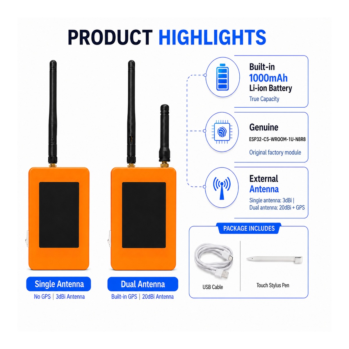
ZLX-ESP32-2
Scheda Sviluppo Display Touch ESP32-C5 2,8 "
1. Panoramica del prodotto
La ZLX-ESP32-2 è una scheda di sviluppo tattile resistiva da 2,8 pollici basata sul modulo ESP32-C5-WROOM-1U-N8R8. Integra un display LCD a colori, controller touch XPT2046, slot per schede microSD/TF (solo slot per schede, esclusa la scheda microSD/TF), interfaccia GPS, uscita audio, rilevamento della tensione della batteria, indicatore LED verde, pulsante di avvio/ripristino e interfaccia dell'antenna esterna. È adatto per lo sviluppo di Wi-Fi 6, Bluetooth LE, Zigbee/Thread, Human Machine Interface (HMI), Data Logging e Internet of Things (IoT).
Caratteristiche principali:
- ESP32-C5 CPU single-core RISC-V a 32 bit a 240 MHz
- ESP32-C5-WROOM-1U-N8R8: 8 MB Flash + 8 MB PSRAM (memoria del modulo integrato, scheda non microSD/TF)
- 2.4 GHz + 5 GHz dual-band Wi-Fi 6 (802.11ax)
- Bluetooth LE、IEEE 802.15.4、Zigbee 3.0、Thread 1.4
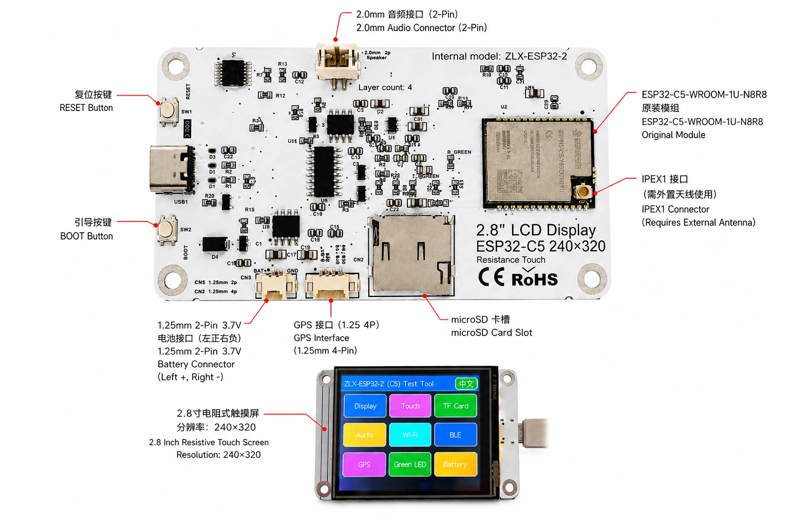
- Display LCD da 2,8 pollici 240 × 320, chip driver ST7789, inizializzazione BGR, la funzione di inversione del display è disabilitata
- Controller touch resistivo XPT2046
- La scheda LCD e TF condividono un'interfaccia SPI, ma l'interfaccia CS è diversa; la funzione touch utilizza un'interfaccia SPI software separata.
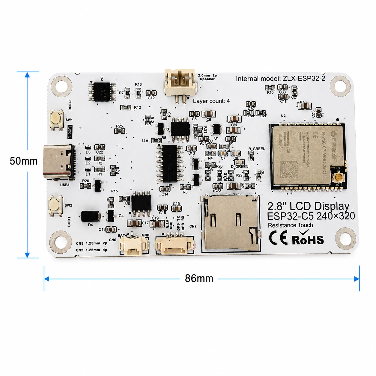
- Dimensioni dei fogli: 86 x 50 mm circa.
- Interfaccia antenna esterna IPEX1; collegare l'antenna esterna appropriata prima di utilizzare la radio.
Utente di destinazione
Per sviluppatori embedded, sviluppatori IoT, maker, usi educativi/di laboratorio e prototipazione di prodotti.
2. Aspetto e dimensioni
La dimensione della scheda è di circa 86 mm x 50 mm. L'immagine seguente aiuta a identificare il display, i connettori e i componenti principali.
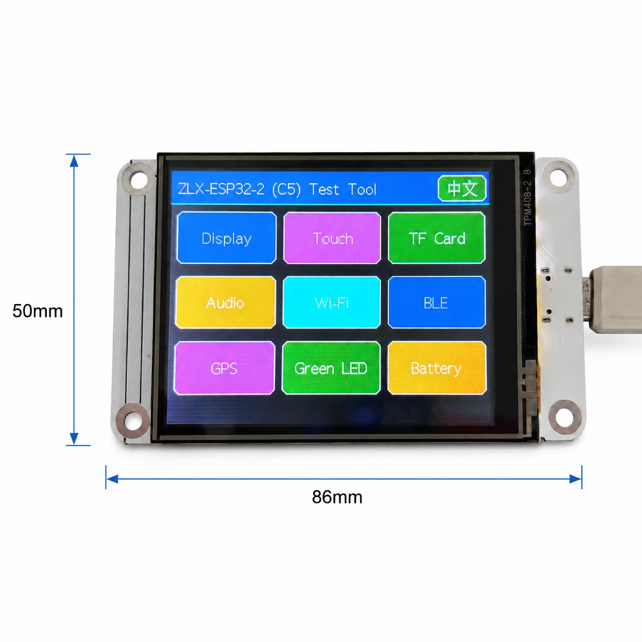
Identificazione del connettore
3. Specifiche della scheda elettronica
| Articolo | FORMATO |
|---|---|
| Modello piastra | ZLX-ESP32-2 |
| Moduli di base | ESP32-C5-WROOM-1U-N8R8 |
| Dimensione piastra | Circa 86 x 50 mm |
| Esposizione | LCD TFT da 2,8 ", chip ST7789, risoluzione originale 240 × 320 |
| Ordine dei colori | Inizializzazione BGR |
| Mostra invertito | Modalità di visualizzazione OFF/Normale |
| Touch | Tocco resistivo XPT2046 |
| slot per schede microSD/TF | Modalità SPI; scheda non inclusa |
| Interfaccia GPS | Connettore a 4 pin da 1,25 mm; segnale UART su GPIO0/GPIO9 |
| Acustico | Altoparlante a 2 pin da 2,0 mm/connettore audio; audio PWM + amplificatore abilitato |
| Batteria | 3.7V monofase, 1.25 mm doppio pin; con circuito di protezione, capacità consigliata 1000–3000mAh |
| Antenna esterna | Connettore IPEX1; necessario per il percorso wireless WROOM-1U |
| BUTTON | Reset, avvio |
| indice | LED verde acceso GPIO26 |
4. Specifiche del modulo ESP32-C5-WROOM-1U-N8R8
I seguenti parametri chiave si basano sulla scheda tecnica ESP32-C5-WROOM-1/WROOM-1U ufficiale di Espressif v1.2.
| Articolo | FORMATO |
|---|---|
| SoC incorporati | ESP32-C5HR8 |
| CPU | Processore single-core RISC-V a 32 bit fino a 240 MHz |
| Rom | 320 KB |
| HP SRAM | 384 KB |
| LP SRAM | 16 KB |
| Flash | 8 MB Quad Channel SPI |
| PSRAM | 8 MB Quad Channel SPI |
| Wifi | 1T1R, 2,4 GHz + 5 GHz dual band; IEEE 802.11ax/ac/b/g/n; fino a 150 Mbps |
| Frequenza 2,4 GHz | 2412–2484 MHz |
| Frequenza 5 GHz | 5180–5885 MHz (soggetto alle normative locali) |
| Bluetooth | Bluetooth Low Energy; l'elenco delle funzionalità di Espressif v1.2 mostra Bluetooth Core 6.0 certificato |
| IEEE 802.15.4 | 2.4 GHz OQPSK,250 Kbps |
| Zigbee/Thread | Zigbee 3.0 / Thread 1.4 |
| GPIO | Sono disponibili fino a 22 GPIO a livello di modulo. |
| Typical Peripherals | GPIO, SPI, UART, I2C, I2S, RMT, LED PWM, USB Serial/JTAG, MCPWM, GDMA, CAN FD, SDIO slave, ADC, temperature sensor, timers, watchdogs, etc. |
| Module Supply | 3.0–3.6 V, typical 3.3 V |
| Recommended Supply Capability | External supply should be capable of at least 0.6 A for the module |
| Ambient Temperature | -40 to +85 °C |
| Module Size | 18.0 × 21.2 × 3.3 mm |
| Antenna | External antenna via connector/module RF path; 50 Ω RF system |
5. Display and Touch
LCD Parameters
| Item | Specification |
|---|---|
| Size | 2.8 inch |
| Driver IC | ST7789 |
| Native resolution | 240 × 320 |
| Landscape logical resolution | 320 × 240 (depending on rotation setting) |
| Color order | BGR |
| Inversion | Disabled / OFF; normal display mode |
| SPI SCK | GPIO6 |
| SPI MOSI | GPIO7 |
| SPI MISO | GPIO2 (shared with TF card; used if required by library/readback) |
| LCD CS | GPIO10 |
| LCD Backlight | GPIO13 |
| LCD DC / RS | GPIO14 |
Touch Parameters
- Touch type: 4-wire resistive; controller: XPT2046.
- DOUT=GPIO3, SCK=GPIO4, DIN=GPIO5.
- CS=GPIO23, IRQ=GPIO25.
- Touch uses an independent software SPI; the supplied test flow is marked as requiring no calibration.
6. GPIO Mapping
The mapping below is based on the supplied GPIO spreadsheet and cross-checked against the schematic. Board peripherals use 19 GPIOs; TX0=GPIO11 and RX0=GPIO12 are additionally used by UART0; GPIO15 is reserved by PSRAM on N8R8, so all 21 usable GPIOs are allocated; EN is not a GPIO.
| GPIO | Signal | Definition | Direction | Function | Notes |
|---|---|---|---|---|---|
| 0 | GPSTX | GPS UART TX | Input | GPS test | GPS module TX → ESP32-C5 |
| 1 | BAT_ADC | Battery voltage sensing | Input/ADC | Battery test | 100k/100k divider; ADC × 2 ≈ battery voltage |
| 2 | SD_MISO | TF DAT0 / LCD MISO shared | Input | TF card test | Shared SPI MISO |
| 3 | RTP_DOUT | XPT2046 DOUT | Input | Touch test | Touch controller data output |
| 4 | RTP_SCK | XPT2046 SCK | Output | Touch test | Independent software SPI |
| 5 | RTP_DIN | XPT2046 DIN | Output | Touch test | Independent software SPI |
| 6 | LCD_SCK | LCD SCK / TF SCK shared | Output | LCD/TF test | Shared SPI clock |
| 7 | LCD_MOSI | LCD MOSI / TF CMD(MOSI) shared | Output | LCD/TF test | Shared SPI MOSI |
| 8 | AUDIOPWM | Audio PWM | Output | Audio test | Audio output control |
| 9 | GPSRX | GPS UART RX | Output | GPS test | ESP32-C5 TX → GPS module RX |
| 10 | LCDCS | ST7789 CS | Output | Display test | LCD chip select |
| 13 | LCDBL | LCD backlight | Output | Display test | Backlight control |
| 14 | LCD_RS/DC | ST7789 DC | Output | Display test | Data/command select |
| 23 | RTPCS | XPT2046 CS | Output | Touch test | Touch chip select |
| 24 | AMP_EN | Amplifier enable | Output | Audio test | High-level enable per supplied mapping; verify actual hardware revision |
| 25 | RTPIRQ | XPT2046 IRQ | Input | Touch test | Touch interrupt |
| 26 | GREENLED | Green LED | Output | LED test | HIGH = ON, LOW = OFF |
| 27 | SDCS | TF DAT3 / CS | Output | TF card test | TF card SPI chip select |
| 28 | BOOTAUTO | BOOT / auto-start control | Input/Control | Factory restore | BOOT input / factory-restore logic |
System and UART Signals
| Signal | Purpose | Note |
|---|---|---|
| RESET_AUTO / EN | ESP32 reset / enable | System enable/reset; not a GPIO |
| UART0_TX / TX0 / GPIO11 | UART0 transmit | Used; excluded from the 19 peripheral GPIO count |
| UART0_RX / RX0 / GPIO12 | UART0 receive | Used; excluded from the 19 peripheral GPIO count |
7. Interface and Bus Sharing
| Item | GPIO | Description |
|---|---|---|
| LCD + TF Shared SPI | GPIO6 / GPIO7 / GPIO2 | SCK, MOSI, MISO shared; devices separated by independent CS |
| LCD CS | GPIO10 | LCD_CS |
| TF card CS | GPIO27 | SD_CS / DAT3 |
| XPT2046 touch | GPIO3 / 4 / 5 / 23 / 25 | DOUT / SCK / DIN / CS / IRQ |
| GPS UART | GPIO0 / GPIO9 | GPSTX / GPSRX; GPIO0 receives GPS TX, GPIO9 drives GPS RX |
| Battery ADC | GPIO1 | BAT_ADC; 100k/100k divider; C20 100 nF filtering |
| Green LED | GPIO26 | HIGH ON, LOW OFF |
| Audio | GPIO8 / GPIO24 | AUDIOPWM / AMP_EN |
| LCD control | GPIO13 / GPIO14 | Backlight / DC |
SPI Sharing Notes
- LCD and TF card share GPIO6 (SCK), GPIO7 (MOSI), and GPIO2 (MISO), but use GPIO10 (LCD_CS) and GPIO27 (SD_CS) respectively.
- Assert only the target device CS at a time to avoid bus contention.
- The XPT2046 touch controller uses an independent software SPI and does not share the main LCD/TF SCK/MOSI signals.
8. Functional Test Mapping
| Test | GPIO | What is tested | Result / Note |
|---|---|---|---|
| Display | GPIO6, 7, 10, 13, 14, 2 | ST7789 display, 240×320 native / 320×240 landscape; BGR; backlight | Normal / Abnormal |
| Touch | GPIO3, 4, 5, 23, 25 | XPT2046 touch response | Test flow: no calibration |
| TF card | GPIO2, 6, 7, 27 | SPI init, read/write/format | Shares SPI with LCD |
| Audio | GPIO8, 24 | PWM audio and amplifier enable | Continuous playback depends on firmware |
| Wi-Fi | Internal RF | 2.4 GHz / 5 GHz scan | No listed GPIO occupied |
| BLE | Internal RF | BLE scan | No listed GPIO occupied |
| GPS | GPIO0, 9 | GPS UART data | GPSTX / GPSRX |
| LED | GPIO26 | Green LED | HIGH on / LOW off |
| Battery | GPIO1 | ADC measures divided battery voltage | Voltage estimate, not a coulomb counter |
| Factory restore | GPIO28 | BOOT input / restore logic | Behavior is defined by firmware |
9. Connector and Electrical Notes
Battery Connector
The board provides a 1.25 mm 2-pin connector for a single-cell 3.7 V battery. In the orientation shown in the labeled image, the left pin is positive (+) and the right pin is negative (-). For battery-powered operation, use a protected single-cell 3.7 V Li-ion/LiPo battery; 1000–3000 mAh is recommended. Verify connector type and polarity before connection. Reverse polarity may damage the board.
Battery Voltage Sensing
GPIO1 senses battery voltage through a 100 kΩ / 100 kΩ divider, so ideally the battery voltage is approximately 2× the ADC pin voltage. This is a voltage estimate only and is not a fuel-gauge/coulomb-counter measurement.
GPS Interface
GPS uses GPIO0 and GPIO9 as UART signals. In this board mapping, GPIO0 (named GPSTX) is an input connected to the GPS module TX, while GPIO9 (named GPSRX) is an output connected to the GPS module RX. For the 1.25 mm 4-pin connector power pins and exact physical pin order, follow the silkscreen/schematic of the specific hardware revision.
External Antenna
ESP32-C5-WROOM-1U is the external-antenna variant. Connect a suitable 2.4/5 GHz, 50-ohm antenna to the IPEX1 connector. Avoid prolonged high-power transmission without a proper antenna attached.
Audio Connector
Audio output uses GPIO8 (AUDIOPWM) for the PWM signal and GPIO24 (AMP_EN) for amplifier enable. The top connector is a 2.0 mm 2-pin audio/speaker connector. Use loads and volume settings within the capability of the actual amplifier circuit.
10. Software Development and Initialization Notes
- Select ST7789 as the display driver and use 240×320 as the native resolution; set rotation for 320×240 landscape as supported by your graphics library.
- Use BGR color order; do not enable display inversion (INVON).
- When LCD and TF share SPI, manage LCD_CS (GPIO10) and SD_CS (GPIO27) independently after initialization.
- XPT2046 utilizza il software standalone SPI su GPIO3/4/5/23/25.
- Per la tensione della batteria, convertire le letture ADC GPIO1 utilizzando un rapporto di tensione parziale di circa 2: 1 e applicare la calibrazione ADC per una maggiore precisione.
- I canali Wi-Fi a 5 GHz disponibili e la potenza di trasmissione dipendono dalle normative locali.
- Il comportamento di avvio/ripristino delle impostazioni di fabbrica è definito dal firmware; si prega di evitare l'attivazione accidentale per evitare di cancellare le impostazioni.
Ordine di inizializzazione suggerito
- Quando l'alimentazione è stabile, inizializzare il sistema ed eseguire il debug dell'UART.
- Inizializzare LCD SPI; configurare ST7789, BGR, disattivare l'inversione e abilitare la retroilluminazione.
- Inizializzare XPT2046 touch.
- Se è necessaria una memoria rimovibile, inserire una scheda microSD/TF compatibile fornita dall'utente, quindi inizializzarla e assicurarsi che lo stato LCD_CS/SD_CS sia corretto.
- Inizializzare GPS, audio, LED e ADC della batteria secondo necessità.
- Abilitare la radio Wi-Fi/BLE/802.15.4 secondo necessità.
11. Risoluzione dei problemi
| Domanda | Soluzioni |
|---|---|
| Mostra schermo vuoto/nero | Controllare GPIO6/7/10/13/14, selezione unità ST7789, impostazioni BGR, GPIO13 retroilluminato e se l'inversione è abilitata accidentalmente. |
| Errore colore | Verificare che la libreria grafica sia configurata per l'ordine dei colori BGR. |
| Nessuna risposta al tocco | Controllare l'inizializzazione di GPIO3/4/5/23/25 e XPT2046. |
| Inizializzazione della scheda TF non riuscita | Controllare l'SPI SCK/MOSI/miso condiviso e assicurarsi che SD_CS (GPIO27) e LCD_CS (GPIO10) non siano impostati contemporaneamente. |
| Segnale Wi-Fi debole/nessun Wi-Fi | Verificare che l'antenna esterna IPEX1 sia collegata e funzioni nella banda GHz 2.4/5. |
| Circa la metà delle letture della batteria | GPIO1 utilizza un partitore di tensione 100k/100k; moltiplicare la tensione lato ADC per circa 2. |
| Nessun dato GPS | Verificare che GPIO0 riceva GPS TX, GPIO9 guidi GPS RX e verifichi la velocità di trasmissione e l'alimentazione. |
12. Download e supporto tecnico
Per il firmware ZLX-ESP32-2, la documentazione, la documentazione di follow-up e il relativo supporto, visitare il Centro di supporto della scheda di sviluppo ZLX ESP32. Prima di far lampeggiare il firmware, assicurati che il modello di PCB mostrato sul sito web corrisponda esattamente al tuo hardware.
Link per il download:https://www.zlxchina.xyz/
Scheda tecnica del modulo Lexin: Scheda tecnica ESP32-C5-WROOM-1/WROOM-1U
Referenze
- Centro di supporto della scheda di sviluppo ZLX ESP32
- Scheda tecnica Espressif ESP32-C5-WROOM-1 & WROOM-1U v1.2 (2026-08-12)
13. Sicurezza e funzionamento
- Controllare la polarità della batteria prima di collegarla; non invertire mai il connettore della batteria.
- Quando si collega e scollega il connettore IPEX, applicare la forza verticalmente ed evitare di fare leva laterale per evitare di danneggiare la presa RF.
- Quando si utilizzano schede a circuito scoperto, adottare misure di protezione dalle scariche elettrostatiche e prevenire cortocircuiti causati da oggetti metallici.
- Le bande radio, i canali e l'alimentazione di trasmissione a 5 GHz devono essere conformi alle normative locali.
- Per le schede TF, GPS, audio e altre periferiche, seguire i livelli di potenza e logici specificati nella versione hardware effettiva. Non applicare un livello logico superiore a 3,3 V ai pin di I/O se non esplicitamente verificato.
14. Cronologia delle revisioni del documento
| - Reverendo! | Data | "Descrizione", | Fondamenta |
|---|---|---|---|
| V1.1 | 2026-08-25 | Istruzioni riviste per schede microSD/TF, batterie e GPIO. | Hefei Zhiluxing Information Technology Co., Ltd. |
Do-re-mi!