ZLX-ESP32-2
ESP32-C5 2.8-inch Touch Display Development Board
中国語と英語のユーザーマニュアル / Bilingual User Manual
Model / モデル: ZLX-ESP32-2
Module / モジュール: ESP32-C5-WROOM-1U-N8R8
Document Version / ドキュメントのバージョン: V1.1 | 2026-08-25
1. 製品概要 / 1. Product Overview
ZLX-ESP32-2 に基づいた製品です ESP32-C5-WROOM-1U-N8R8 モジュラー 2.8 カラーを統合したインチ抵抗膜タッチスクリーン開発ボード LCD、XPT2046 触る、microSD/TF カードスロット(カードスロットのみ、付属しません) microSD/TF カード)、GPS インターフェース、オーディオ出力、バッテリー電圧検出、グリーン LED、BOOT/RESET ボタンと外部アンテナのインターフェイス。適切な Wi-Fi 6、Bluetooth LE、Zigbee/Thread、ヒューマン マシン インターフェイス、データ記録、モノのインターネット アプリケーション開発。
ZLX-ESP32-2 is a 2.8-inch resistive-touch development board based on the ESP32-C5-WROOM-1U-N8R8 module. It integrates a color LCD, XPT2046 touch controller, a microSD/TF card slot (slot only; no microSD/TF card is included), GPS interface, audio output, battery-voltage sensing, green LED, BOOT/RESET buttons, and an external-antenna connector. It is suitable for Wi-Fi 6, Bluetooth LE, Zigbee/Thread, HMI, data logging, and IoT development.
主な特長 / Key Features
ESP32-C5 32 少し RISC-V シングルコアプロセッサ、最大 240 MHz / ESP32-C5 32-bit RISC-V single-core CPU, up to 240 MHz
ESP32-C5-WROOM-1U-N8R8:8 MB Flash + 8 MB PSRAM(モジュールのオンボード リソースではなく、 microSD/TF カード) / ESP32-C5-WROOM-1U-N8R8: 8 MB Flash + 8 MB PSRAM (onboard module memory, not a microSD/TF card)
2.4 GHz + 5 GHz デュアルバンド Wi-Fi 6(802.11ax) / 2.4 GHz + 5 GHz dual-band Wi-Fi 6 (802.11ax)
Bluetooth LE、IEEE 802.15.4、Zigbee 3.0、Thread 1.4 / Bluetooth LE, IEEE 802.15.4, Zigbee 3.0, Thread 1.4
2.8 インチ 240×320 LCD,ST7789 ドライブ、BGR 初期化、反転カラーを無効にする / 2.8-inch 240×320 LCD, ST7789 driver, BGR initialization, display inversion disabled
XPT2046 抵抗タッチコントローラー / XPT2046 resistive touch controller
LCD そして TF カードシェアリング SPI バス、独立した CS;タッチしてスタンドアロン ソフトウェアを使用します SPI / LCD and TF card share SPI with separate CS; touch uses an independent software SPI
ボードサイズ約 86 mm × 50 mm / Board size approx. 86 mm × 50 mm
IPEX1 外部アンテナインターフェイス。ワイヤレス機能を使用する前に、外部アンテナを正しく接続する必要があります / IPEX1 external antenna connector; connect a suitable external antenna before radio use
適用対象 / Intended Users
組み込み開発者、IoT 開発者、メーカー、教育実験や製品プロトタイプ設計に適しています。
For embedded developers, IoT developers, makers, education/lab use, and product prototyping.
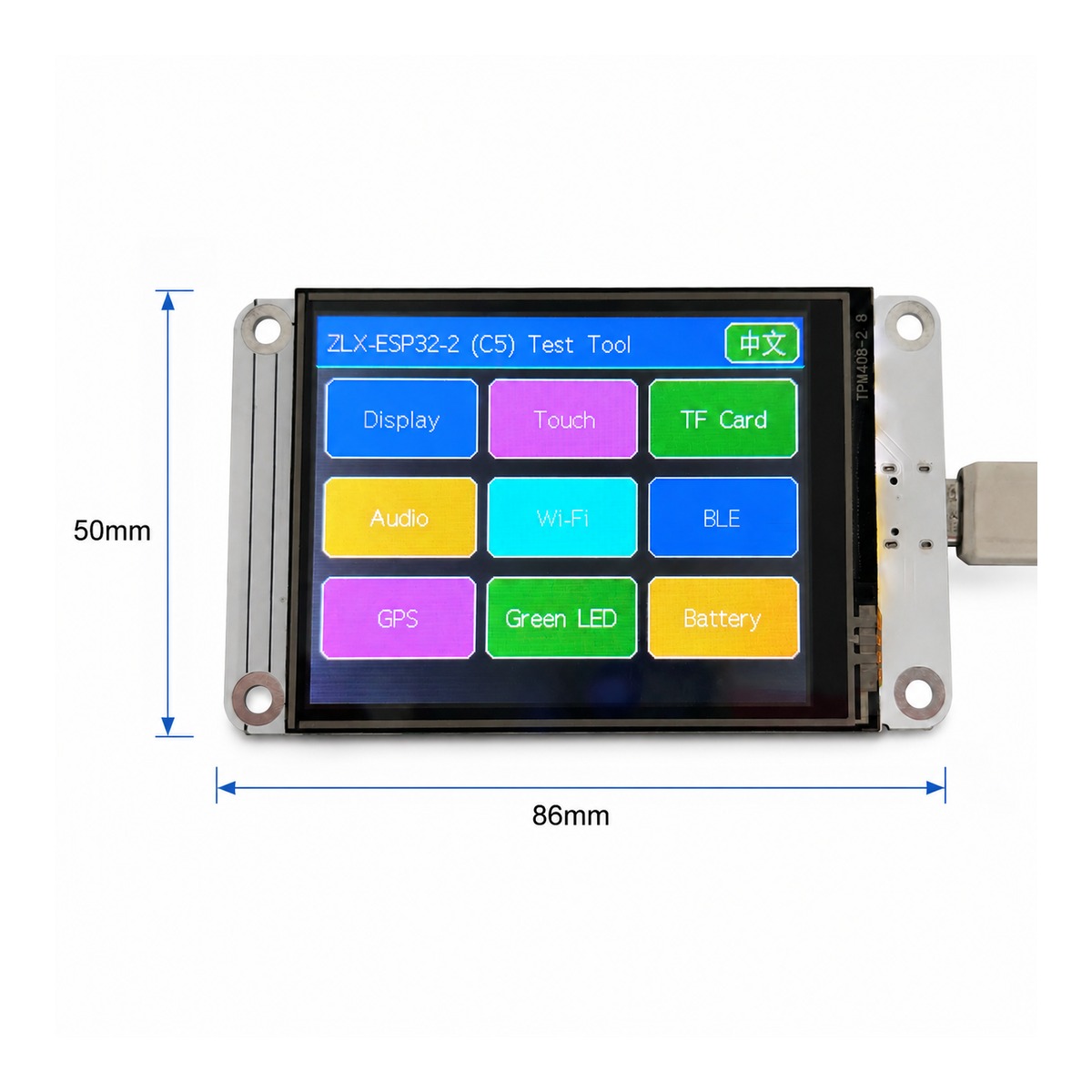
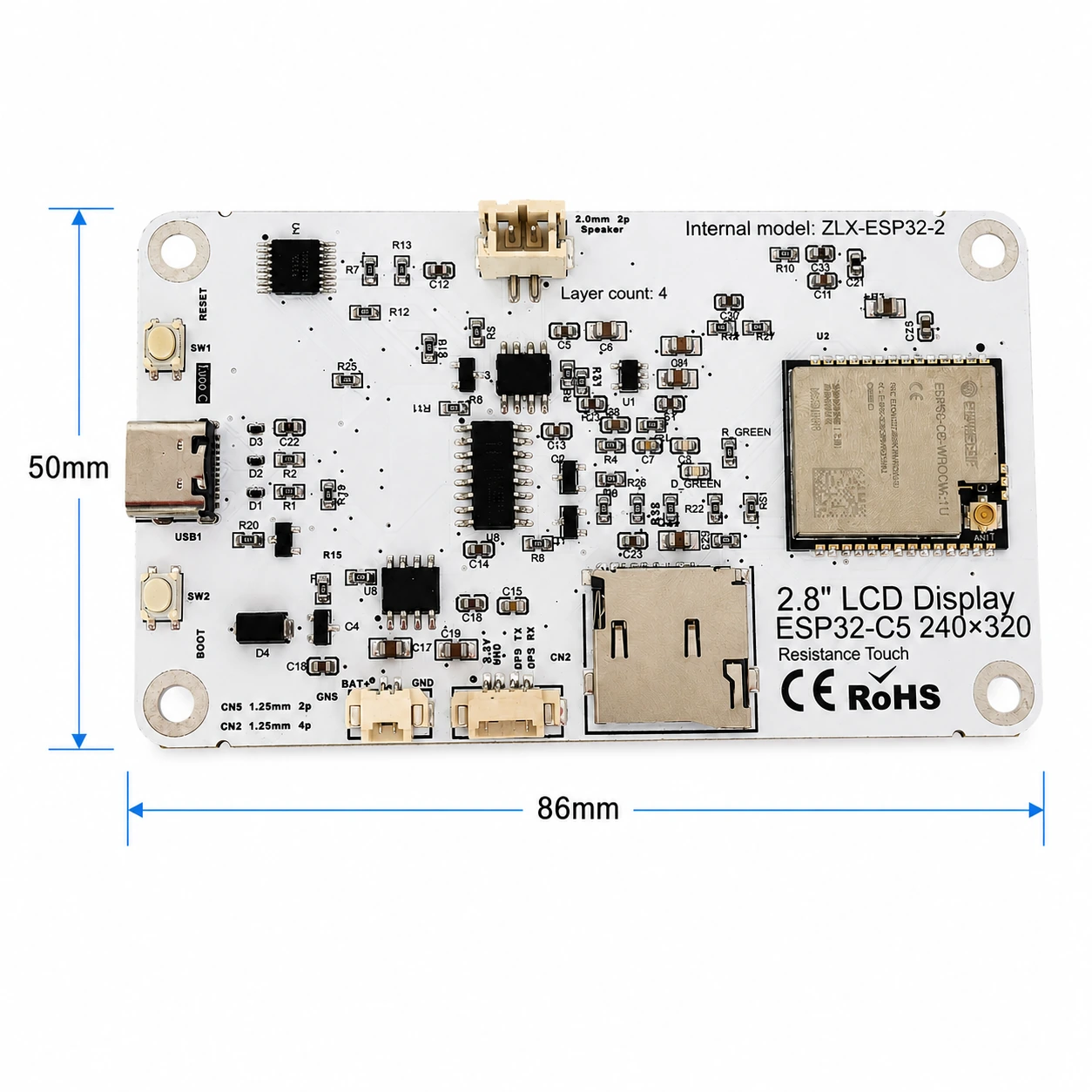
2. 外観とサイズ / 2. Appearance and Dimensions
ボード全体の寸法はおよそです。 86 mm × 50 mm。次の前面と背面の図は、画面、インターフェイス、および主要コンポーネントを識別するために使用されます。
The board outline is approximately 86 mm × 50 mm. The images below help identify the display, connectors, and major components.
|
|
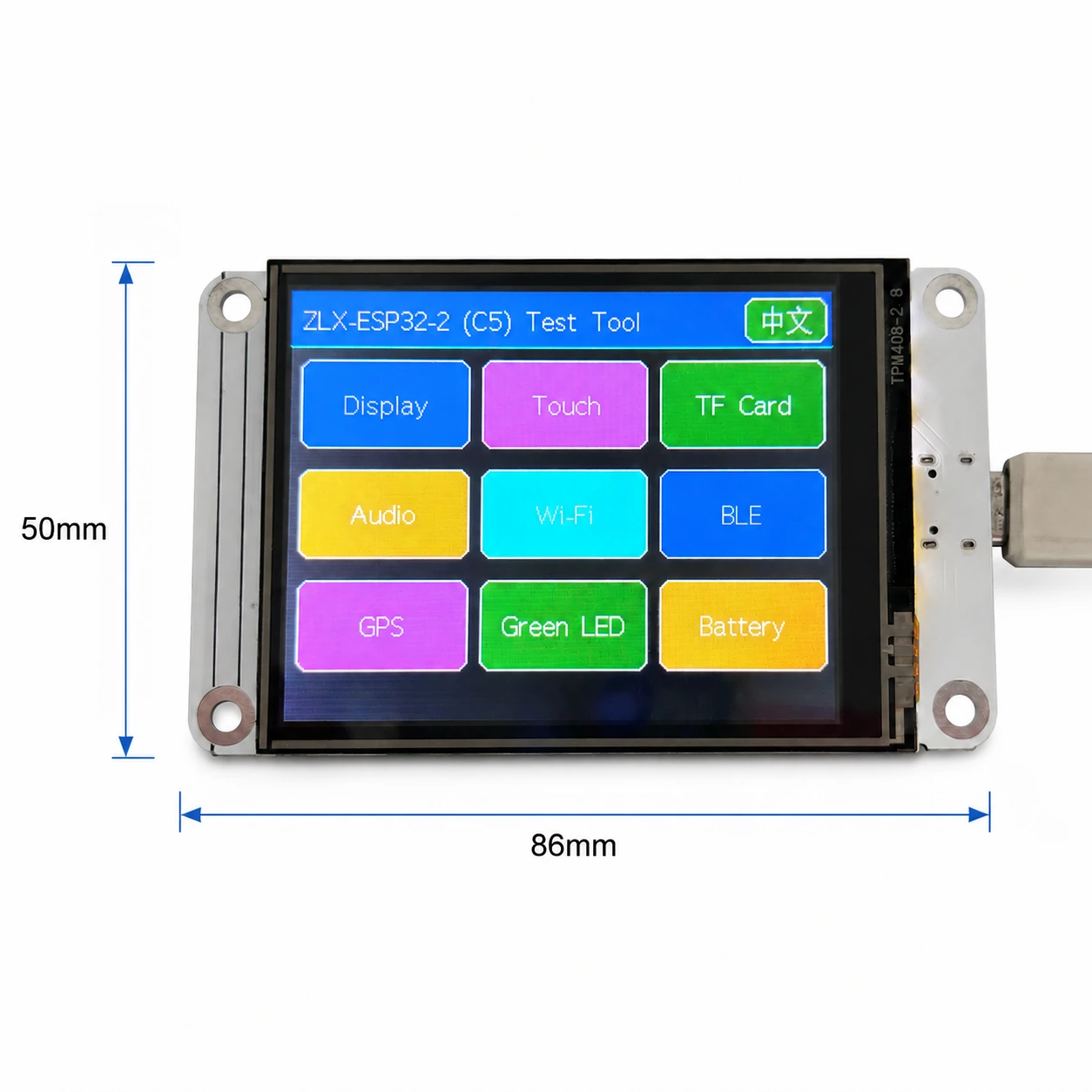
写真 1 前面および画面の寸法 / Figure 1 Board front and display-side dimensions
インターフェースの注釈 / Connector Identification
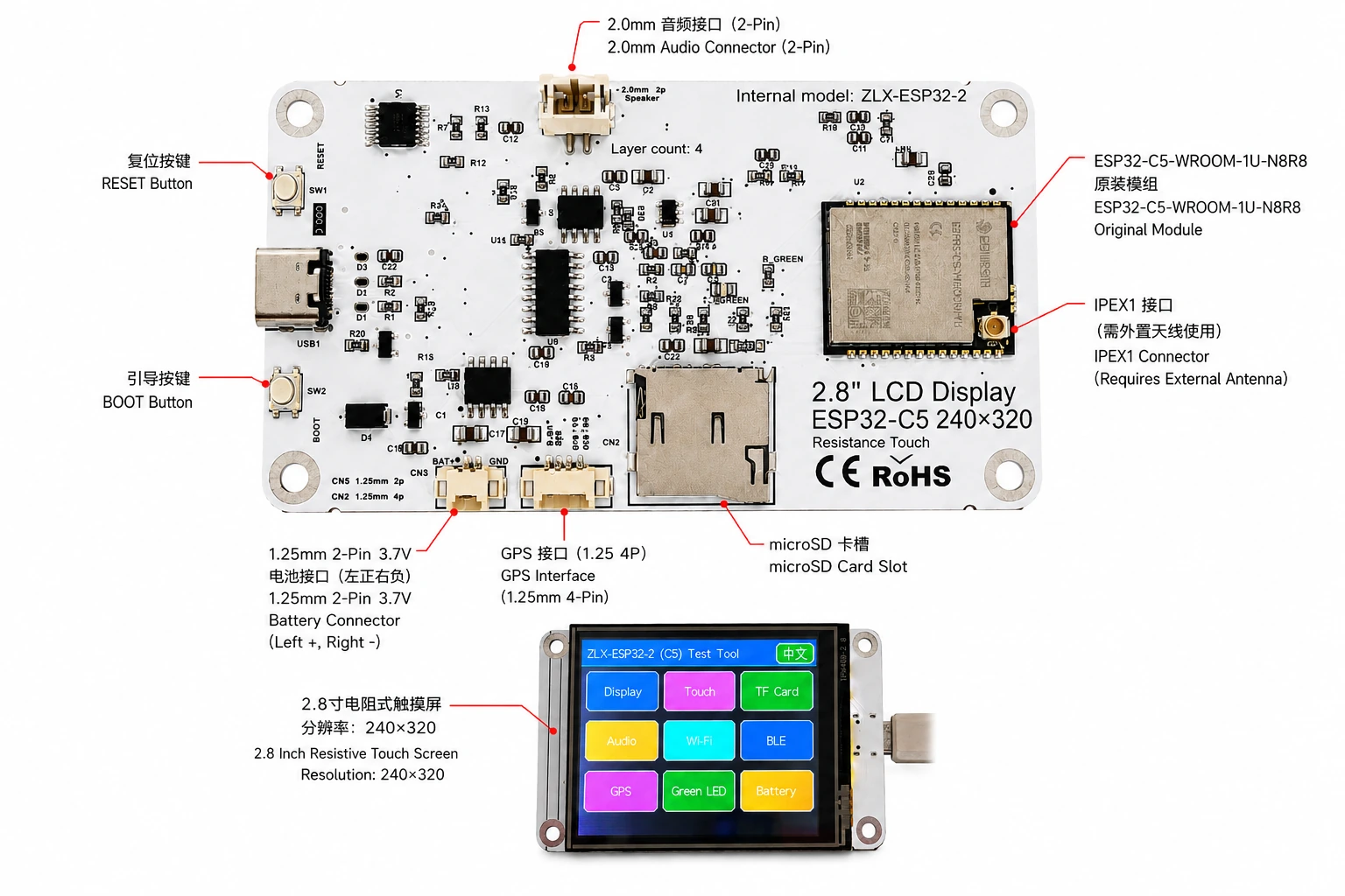
写真 2 ZLX-ESP32-2 中国語と英語のインターフェース注釈 / Figure 2 Bilingual connector identification
3. 開発ボードの仕様 / 3. Board Specifications
プロジェクト / Item | 仕様 / Specification |
開発ボードのモデル / Board model | ZLX-ESP32-2 |
コアモジュール / Core module | ESP32-C5-WROOM-1U-N8R8 |
基板サイズ / Board size | Approx. 86 × 50 mm |
画面 / Display | 2.8-inch TFT LCD, ST7789, 240×320 native resolution |
色の順序 / Color order | BGR initialization |
逆色を表示 / Display inversion | OFF / Normal display mode(反転カラーはオンにしないでください) |
触る / Touch | Resistive touch / 抵抗膜タッチ, XPT2046 |
microSD/TF カードスロット / microSD/TF Card Slot | SPI mode; card not included / SPI モード;カードは付属しません |
GPS インタフェース / GPS interface | 1.25 mm 4-pin connector; UART signals on GPIO0/GPIO9 |
オーディオインターフェース / Audio | 2.0 mm 2-pin speaker/audio connector; PWM audio + amplifier enable |
バッテリーインターフェース / Battery | 3.7 V 1S, 1.25 mm 2-pin; protected 1000–3000 mAh recommended / 単一セクション 3.7 V;提案 1000–3000 mAh 保護板付き |
外部アンテナ / External antenna | IPEX1 connector; required for the WROOM-1U radio path |
ボタン / Buttons | RESET, BOOT |
ステータス表示 / Indicator | Green LED on GPIO26 |
説明する / Note: ネイティブの画面解像度は次のとおりです。 240×320; ソフトウェアが水平画面回転に設定されている場合、論理表示サイズは次のように表すことができます。 320×240。 / The panel native resolution is 240×320; in landscape rotation, the logical display size may be 320×240.
4. ESP32-C5-WROOM-1U-N8R8 モジュールパラメータ / 4. ESP32-C5-WROOM-1U-N8R8 Module Specifications
次の主要なパラメータは以下に基づいています。 Espressif 正式 ESP32-C5-WROOM-1 / WROOM-1U Datasheet v1.2。
The following key parameters are based on Espressif's official ESP32-C5-WROOM-1 / WROOM-1U Datasheet v1.2.
プロジェクト / Item | 仕様 / Specification |
内蔵チップ / Embedded SoC | ESP32-C5HR8 |
CPU | 32-bit RISC-V single core, up to 240 MHz |
ROM | 320 KB |
HP SRAM | 384 KB |
LP SRAM | 16 KB |
Flash | 8 MB Quad SPI |
PSRAM | 8 MB Quad SPI |
Wi-Fi | 1T1R, 2.4 GHz + 5 GHz dual-band; IEEE 802.11ax/ac/b/g/n; up to 150 Mbps |
2.4 GHz 頻度 / Frequency | 2412–2484 MHz |
5 GHz 頻度 / Frequency | 5180–5885 MHz (subject to regional regulations) |
Bluetooth | Bluetooth LE; Espressif v1.2 feature list states Bluetooth Core 6.0 certified |
IEEE 802.15.4 | 2.4 GHz OQPSK, 250 Kbps |
Zigbee / Thread | Zigbee 3.0 / Thread 1.4 |
GPIO | Up to 22 GPIOs at module level |
代表的な周辺機器 / Peripherals | GPIO, SPI, UART, I2C, I2S, RMT, LED PWM, USB Serial/JTAG, MCPWM, GDMA, CAN FD, SDIO slave, ADC, temperature sensor, timers, watchdogs, etc. |
モジュール動作電圧 / Module supply | 3.0–3.6 V, typical 3.3 V |
推奨される電力機能 / Recommended supply capability | External supply should be capable of at least 0.6 A for the module |
周囲温度 / Ambient temperature | -40 to +85 °C |
モジュールサイズ / Module size | 18.0 × 21.2 × 3.3 mm |
アンテナ / Antenna | External antenna via connector/module RF path; 50 Ω RF system |
5. 表示とタッチ / 5. Display and Touch
LCD パラメータ / LCD Parameters
プロジェクト / Item | 仕様 / Specification |
サイズ / Size | 2.8 inch |
ドライブ IC / Driver IC | ST7789 |
ネイティブ解像度 / Native resolution | 240 × 320 |
水平画面の論理解像度 / Landscape logical resolution | 320 × 240 (depending on rotation setting) |
色の順序 / Color order | BGR |
逆色 / Inversion | Disabled / OFF; normal display mode |
SPI クロック / SCK | GPIO6 |
SPI MOSI | GPIO7 |
SPI MISO | GPIO2 (shared with TF card; used if required by library/readback) |
LCD CS | GPIO10 |
LCD Backlight / バックライト | GPIO13 |
LCD DC / RS | GPIO14 |
タッチパラメータ / Touch Parameters
タッチタイプ:4 ワイヤー抵抗タッチ;コントローラ:XPT2046。 / Touch type: 4-wire resistive; controller: XPT2046.
DOUT=GPIO3,SCK=GPIO4,DIN=GPIO5。 / DOUT=GPIO3, SCK=GPIO4, DIN=GPIO5.
CS=GPIO23,IRQ=GPIO25。 / CS=GPIO23, IRQ=GPIO25.
タッチしてスタンドアロン ソフトウェアを使用する SPI; 検出ツールのプロセスはキャリブレーションを必要としないとしてマークされています。 / Touch uses an independent software SPI; the supplied test flow is marked as requiring no calibration.
6. GPIO マッピング / 6. GPIO Mapping
次のマッピングは、ボードに付属の顧客バージョンからのものです。 GPIO スプレッドシートと回路図と照合します。オンボード周辺機器の使用 19 普通の GPIO;TX0=GPIO11、RX0=GPIO12 にも使用されます UART0;N8R8 の GPIO15 キルト PSRAM 占領されているため、 21 利用可能 GPIO すべて割り当てられています。EN 仕事としてカウントされない GPIO。
The mapping below is based on the supplied GPIO spreadsheet and cross-checked against the schematic. Board peripherals use 19 GPIOs; TX0=GPIO11 and RX0=GPIO12 are additionally used by UART0; GPIO15 is reserved by PSRAM on N8R8, so all 21 usable GPIOs are allocated; EN is not a GPIO.
GPIO | Signal | 意味 / Definition | 方向性 / Direction | 関数 / Function | 説明する / Notes |
0 | GPSTX | GPS シリアルポート TX / GPS UART TX | Input / 入力 | GPS test / GPSテスト | GPS module TX → ESP32-C5 |
1 | BAT_ADC | バッテリー電圧検出 / Battery voltage sensing | Input/ADC | Battery test | 100k/100k divider; ADC × 2 ≈ battery voltage |
2 | SD_MISO | TF DAT0 / LCD MISO 共有 / Shared | Input | TF card test | Shared SPI MISO |
3 | RTP_DOUT | XPT2046 DOUT | Input | Touch test | Touch controller data output |
4 | RTP_SCK | XPT2046 SCK | Output | Touch test | Independent software SPI |
5 | RTP_DIN | XPT2046 DIN | Output | Touch test | Independent software SPI |
6 | LCD_SCK | LCD SCK / TF SCK 共有 / Shared | Output | LCD/TF test | Shared SPI clock |
7 | LCD_MOSI | LCD MOSI / TF CMD(MOSI) 共有 / Shared | Output | LCD/TF test | Shared SPI MOSI |
8 | AUDIOPWM | オーディオ PWM / Audio PWM | Output | Audio test | Audio output control |
9 | GPSRX | GPS シリアルポート RX / GPS UART RX | Output | GPS test | ESP32-C5 TX → GPS module RX |
10 | LCDCS | ST7789 CS | Output | Display test | LCD chip select |
13 | LCDBL | LCD バックライト / LCD backlight | Output | Display test | Backlight control |
14 | LCD_RS/DC | ST7789 DC | Output | Display test | Data/command select |
23 | RTPCS | XPT2046 CS | Output | Touch test | Touch chip select |
24 | AMP_EN | アンプ有効 / Amplifier enable | Output | Audio test | High-level enable per supplied mapping; verify actual hardware revision |
25 | RTPIRQ | XPT2046 IRQ | Input | Touch test | Touch interrupt |
26 | GREENLED | 緑 LED / Green LED | Output | LED test | HIGH = ON, LOW = OFF |
27 | SDCS | TF DAT3 / CS | Output | TF card test | TF card SPI chip select |
28 | BOOTAUTO | BOOT / 自動始動制御 / auto-start control | Input/Control | Factory restore | BOOT input / factory-restore logic |
システム信号とシリアルポート信号 / System and UART Signals
信号 / Signal | 使用 / Purpose | 述べる / Note |
RESET_AUTO / EN | ESP32 reset / enable / ESP32 リセットして有効にする | System enable/reset; not a GPIO / システムイネーブル/リセット、属していない GPIO |
UART0_TX / TX0 / GPIO11 | UART0 transmit / UART0 シリアルポート送信 | Used; excluded from the 19 peripheral GPIO count / 使用済み;上記にはカウントされません 19 周辺機器 GPIO |
UART0_RX / RX0 / GPIO12 | UART0 receive / UART0 シリアルポート受信 | Used; excluded from the 19 peripheral GPIO count / 使用済み;上記にはカウントされません 19 周辺機器 GPIO |
7. インターフェイスとバスの共有命令 / 7. Interface and Bus Sharing
プロジェクト / Item | GPIO | 説明する / Description |
LCD + TF SPI 共有 / Shared SPI | GPIO6 / GPIO7 / GPIO2 | SCK, MOSI, MISO shared; devices separated by independent CS / クロックとデータラインを共有し、独立して使用 CS デバイスを区別する |
LCD CS | GPIO10 | LCD_CS |
TF card CS | GPIO27 | SD_CS / DAT3 |
XPT2046 touch | GPIO3 / 4 / 5 / 23 / 25 | DOUT / SCK / DIN / CS / IRQ |
GPS UART | GPIO0 / GPIO9 | GPSTX / GPSRX; GPIO0 receives GPS TX, GPIO9 drives GPS RX |
Battery ADC | GPIO1 | BAT_ADC; 100k/100k divider; C20 100 nF filtering |
Green LED | GPIO26 | HIGH ON, LOW OFF |
Audio | GPIO8 / GPIO24 | AUDIOPWM / AMP_EN |
LCD control | GPIO13 / GPIO14 | Backlight / DC |
SPI 共有の考慮事項 / SPI Sharing Notes
LCD そして TF カードシェアリング GPIO6(SCK)、GPIO7(MOSI)、GPIO2(MISO)、ただしそれぞれを使用します GPIO10(LCD_CS) そして GPIO27(SD_CS)。 / LCD and TF card share GPIO6 (SCK), GPIO7 (MOSI), and GPIO2 (MISO), but use GPIO10 (LCD_CS) and GPIO27 (SD_CS) respectively.
同時にターゲットデバイスのみを有効にする CS、複数のデバイスが同時に選択されることによって引き起こされるバスの競合を回避します。 / Assert only the target device CS at a time to avoid bus contention.
触る XPT2046 スタンドアロン ソフトウェアを使用する SPI、ではありません LCD/TF 主 SPI 時計と MOSI 共有されました。 / The XPT2046 touch controller uses an independent software SPI and does not share the main LCD/TF SCK/MOSI signals.
8. 検知機能対応 / 8. Functional Test Mapping
試験項目 / Test | GPIO | 検出内容 / What is tested | 結果/説明する / Result/Note |
スクリーンテスト / Display | GPIO6, 7, 10, 13, 14, 2 | ST7789 display, 240×320 native / 320×240 landscape; BGR; backlight | Normal / Abnormal |
タッチテスト / Touch | GPIO3, 4, 5, 23, 25 | XPT2046 touch response | Test flow: no calibration |
TF カードテスト / TF card | GPIO2, 6, 7, 27 | SPI init, read/write/format | Shares SPI with LCD |
オーディオテスト / Audio | GPIO8, 24 | PWM audio and amplifier enable | Continuous playback depends on firmware |
Wi-Fi テスト / Wi-Fi | Internal RF | 2.4 GHz / 5 GHz scan | No listed GPIO occupied |
BLE テスト / BLE | Internal RF | BLE scan | No listed GPIO occupied |
GPS テスト / GPS | GPIO0, 9 | GPS UART data | GPSTX / GPSRX |
LED テスト / LED | GPIO26 | Green LED | HIGH on / LOW off |
バッテリーテスト / Battery | GPIO1 | ADC measures divided battery voltage | Voltage estimate, not a coulomb counter |
BOOT 工場出荷時設定にリセット / Factory restore | GPIO28 | BOOT input / restore logic | Behavior is defined by firmware |
9. インターフェースと電気的考慮事項 / 9. Connector and Electrical Notes
バッテリーインターフェース / Battery Connector
開発ボードが提供されています 1.25 mm 2-Pin 3.7 V シングルバッテリーインターフェース。マークした図の見る方向に応じて、左側が正極になります(+)、右側がマイナス極 (-)。バッテリー電源が必要な場合は、容量を使用することをお勧めします 1000–3000 mAh、保護基板(保護回路)付き単段 3.7 V リチウムイオン/リチウムポリマー電池を接続する前に、インターフェイスの仕様とプラス極とマイナス極を確認してください。逆接続すると開発ボードが損傷する可能性があります。
The board provides a 1.25 mm 2-pin connector for a single-cell 3.7 V battery. In the orientation shown in the labeled image, the left pin is positive (+) and the right pin is negative (-). For battery-powered operation, use a protected single-cell 3.7 V Li-ion/LiPo battery; 1000–3000 mAh is recommended. Verify connector type and polarity before connection. Reverse polarity may damage the board.
GPIO1 合格 100 kΩ / 100 kΩ 分圧器ネットワークはバッテリー電圧を検出するため、理想的な環境下では実際のバッテリー電圧は約 ADC ピン電圧 2 回。この機能は電圧推定のみを目的としており、燃料クーロンメーターではありません。
GPIO1 senses battery voltage through a 100 kΩ / 100 kΩ divider, so ideally the battery voltage is approximately 2× the ADC pin voltage. This is a voltage estimate only and is not a fuel-gauge/coulomb-counter measurement.
GPS インタフェース / GPS Interface
GPS 使用 GPIO0 そして GPIO9 として UART 信号。GPIO0(GPSTX という名前) をこのボード定義の入力として接続します。 GPS モジュール TX;GPIO9(GPSRX 名前付き) を出力として接続します GPS モジュール RX。1.25 mm 4-Pin コネクタの電源ピンと実際のピン配列については、対応するハードウェア バージョンを参照してください。/概略図が優先されます。
GPS uses GPIO0 and GPIO9 as UART signals. In this board mapping, GPIO0 (named GPSTX) is an input connected to the GPS module TX, while GPIO9 (named GPSRX) is an output connected to the GPS module RX. For the 1.25 mm 4-pin connector power pins and exact physical pin order, follow the silkscreen/schematic of the specific hardware revision.
外部アンテナ / External Antenna
ESP32-C5-WROOM-1U 外部アンテナ版です。ボード IPEX1 インターフェイスは次のように接続する必要があります 2.4/5 GHz 周波数帯域のマッチングとインピーダンスは、 50 Ω アンテナ。適切なアンテナを接続せずに、長時間高出力で送信しないでください。
ESP32-C5-WROOM-1U is the external-antenna variant. Connect a suitable 2.4/5 GHz, 50-ohm antenna to the IPEX1 connector. Avoid prolonged high-power transmission without a proper antenna attached.
オーディオインターフェース / Audio Connector
オーディオ出力は次によって提供されます。 GPIO8(AUDIOPWM)生産する PWM 信号、GPIO24(AMP_EN) パワーアンプのイネーブルを制御します。ボードの上部は 2.0 mm 2-Pin オーディオ/スピーカーインターフェイス。さまざまな負荷とボリューム設定については、実際のパワーアンプ回路の能力を参照してください。
Audio output uses GPIO8 (AUDIOPWM) for the PWM signal and GPIO24 (AMP_EN) for amplifier enable. The top connector is a 2.0 mm 2-pin audio/speaker connector. Use loads and volume settings within the capability of the actual amplifier circuit.
10. ソフトウェア開発と初期化に関するアドバイス / 10. Software Development and Initialization Notes
ディスプレイドライバーの選択 ST7789、ネイティブ解像度は次のように設定されます。 240×320;横画面を回転させることができます 320×240。 / Select ST7789 as the display driver and use 240×320 as the native resolution; set rotation for 320×240 landscape as supported by your graphics library.
使用される色の順序 BGR;反転色の表示を有効にしないでください(INVON)。 / Use BGR color order; do not enable display inversion (INVON).
LCD/TF 共有 SPI いつ、初期化後に個別に管理される LCD_CS(GPIO10) そして SD_CS(GPIO27)。 / When LCD and TF share SPI, manage LCD_CS (GPIO10) and SD_CS (GPIO27) independently after initialization.
XPT2046 使用 GPIO3/4/5/23/25 独立したソフトウェア SPI。 / XPT2046 uses an independent software SPI on GPIO3/4/5/23/25.
バッテリー電圧を読み取る場合、 GPIO1 の ADC 結果は約 2:1 分圧比変換と組み合わせ ADC キャリブレーションにより精度が向上します。 / For battery voltage, convert the GPIO1 ADC reading using the approximately 2:1 divider ratio and apply ADC calibration for better accuracy.
Wi-Fi 5 GHz 利用可能なチャンネルと送信出力は国によって異なります/地域の規制制限。 / Available 5 GHz Wi-Fi channels and transmit power depend on local regulations.
BOOT/工場出荷時設定へのリセットロジックはファームウェアによって決定されます。動作中に誤ってトリガーされ、設定がクリアされることを回避します。 / BOOT/factory-restore behavior is firmware-defined; avoid unintended activation that may clear settings.
推奨される初期化シーケンス / Suggested Initialization Sequence
1. 電源が安定してからシステムとシリアルポートを初期化します。
After power is stable, initialize the system and debug UART.
2. 初期化 LCD SPI、設定 ST7789、BGR、反転色をオフにしてから、バックライトをオンにします。
Initialize LCD SPI; configure ST7789, BGR, inversion off, then enable backlight.
3. 初期化 XPT2046 触る。
Initialize XPT2046 touch.
4. ストレージ機能を使用する必要がある場合は、ユーザーが用意した互換性のあるストレージ機能を挿入してください。 microSD/TF カードを再初期化して確認します LCD_CS そして SD_CS ステータスは正しいです。
If removable storage is required, insert a compatible user-supplied microSD/TF card, then initialize it and ensure correct LCD_CS/SD_CS states.
5. オンデマンドで初期化する GPS、オーディオ、LED、バッテリー ADC。
Initialize GPS, audio, LED, and battery ADC as needed.
6. 最後に有効にした Wi-Fi/BLE/802.15.4 ワイヤレス機能。
Enable Wi-Fi/BLE/802.15.4 radio functions as required.
11. 一般的な問題のトラブルシューティング / 11. Troubleshooting
質問 / Issue | English | 治療方法 / Solution | Solution (EN) |
白い画面/黒い画面 | Blank/black display | 診る GPIO6/7/10/13/14、ST7789 ドライバーの選択、BGR 設定、バックライト GPIO13 そして、誤って反転色をオンにしてしまったかどうか。 | Check GPIO6/7/10/13/14, ST7789 driver selection, BGR setting, backlight GPIO13, and whether inversion was accidentally enabled. |
色が間違っています | Incorrect colors | グラフィックス ライブラリの色の順序が次のとおりであることを確認します。 BGR。 | Confirm the graphics library is configured for BGR color order. |
タッチしても反応しない | No touch response | 診る GPIO3/4/5/23/25 そして XPT2046 初期化。 | Check GPIO3/4/5/23/25 and XPT2046 initialization. |
TF カードの初期化に失敗しました | TF card init fails | 診る LCD/TF 共有 SPI の SCK/MOSI/MISO、同様に SD_CS(GPIO27) そして LCD_CS(GPIO10) 競合があるかどうか。 | Check shared SPI SCK/MOSI/MISO and make sure SD_CS (GPIO27) and LCD_CS (GPIO10) are not asserted simultaneously. |
Wi-Fi 信号が弱いかスキャンできません | Weak/no Wi-Fi | 確認する IPEX1 外部アンテナは次を使用して接続およびサポートされます。 2.4/5 GHz 適切なアンテナ。 | Confirm the IPEX1 external antenna is connected and suitable for 2.4/5 GHz. |
バッテリー電圧の測定値は実際の約半分です | Battery reading is about half | GPIO1 フロントエンドは 100k/100k 換算する際は分圧を約倍する必要があります 2。 | GPIO1 uses a 100k/100k divider; multiply the ADC-side voltage by approximately 2. |
GPS データなし | No GPS data | 確認する GPIO0 キャッチ GPS TX、GPIO9 キャッチ GPS RX、ボーレートと電源を確認してください。 | Confirm GPIO0 receives GPS TX, GPIO9 drives GPS RX, and verify baud rate and power. |
12. データのダウンロードと技術サポート / 12. Downloads and Technical Support
ZLX-ESP32-2 ファームウェア、ファイル、フォローアップ情報、および関連サポートへの優先アクセスを許可してください。 ZLX ESP32 開発ボードメーカーサポートセンター。ファームウェアをフラッシュする前に、ページに記載されている内容をご確認ください。 PCB モデルは手持ちのボードと全く同じです。
For ZLX-ESP32-2 firmware, files, future documentation, and related support, use the ZLX ESP32 development-board support center. Before flashing firmware, confirm the PCB model shown on the website exactly matches your hardware.
データダウンロード / Downloads: https://www.zlxchina.xyz/
Espressif module datasheet / Espressif モジュールの仕様: ESP32-C5-WROOM-1 / WROOM-1U Datasheet
参考文献 / References
ZLX ESP32 開発ボードメーカーサポートセンター / ZLX ESP32 Development Board Support Center — https://www.zlxchina.xyz/
Espressif ESP32-C5-WROOM-1 & WROOM-1U Datasheet v1.2 (2026-08-12) / Espressif ESP32-C5-WROOM-1 & WROOM-1U Datasheet v1.2 (2026-08-12) — https://espressif.com/documentation/esp32-c5-wroom-1_wroom-1u_datasheet_en.pdf
13. 使用上の注意と安全上の注意 / 13. Safety and Handling
バッテリーを接続する前にプラス極とマイナス極を確認する必要があり、逆接続は禁止されています。 / Verify battery polarity before connection; never reverse the battery connector.
抜き差しする IPEX アンテナを接続するときは、RF ベースの脱落を引き起こす可能性のある横方向のこじりを避けるために、垂直方向の力を維持してください。 / When mating/unmating the IPEX connector, apply force vertically and avoid sideways prying that may damage the RF socket.
開発ボードのベアボードを使用する場合は、金属物体による短絡を避けるために静電気保護に注意してください。 / Use ESD precautions with the bare board and prevent metal objects from causing shorts.
5 GHz 無線周波数帯域、チャネル、および電力は、使用地域の規制に準拠する必要があります。 / 5 GHz radio band, channels, and transmit power must comply with local regulations.
TF カード、GPSオーディオやビデオなどの周辺機器の電源供給能力やレベルについては、実際のハードウェアのバージョンに従ってください。確認なしに連絡しないでください。 IO 上に適用されたピン 3.3 V レベル。 / For TF, GPS, audio, and other peripherals, follow the actual hardware revision for supply and logic levels. Do not apply logic levels above 3.3 V to IO pins unless explicitly verified.
14. ドキュメントのバージョン記録 / 14. Document Revision History
バージョン / Rev. | 日付 / Date | コンテンツ / Description | ソース / Basis |
V1.1 | 2026-08-25 | リビジョン:microSD/TF、バッテリーと GPIO 説明します。 | Hefei Zhiluxing Information Technology Co., Ltd. |
— End / 仕上げる -