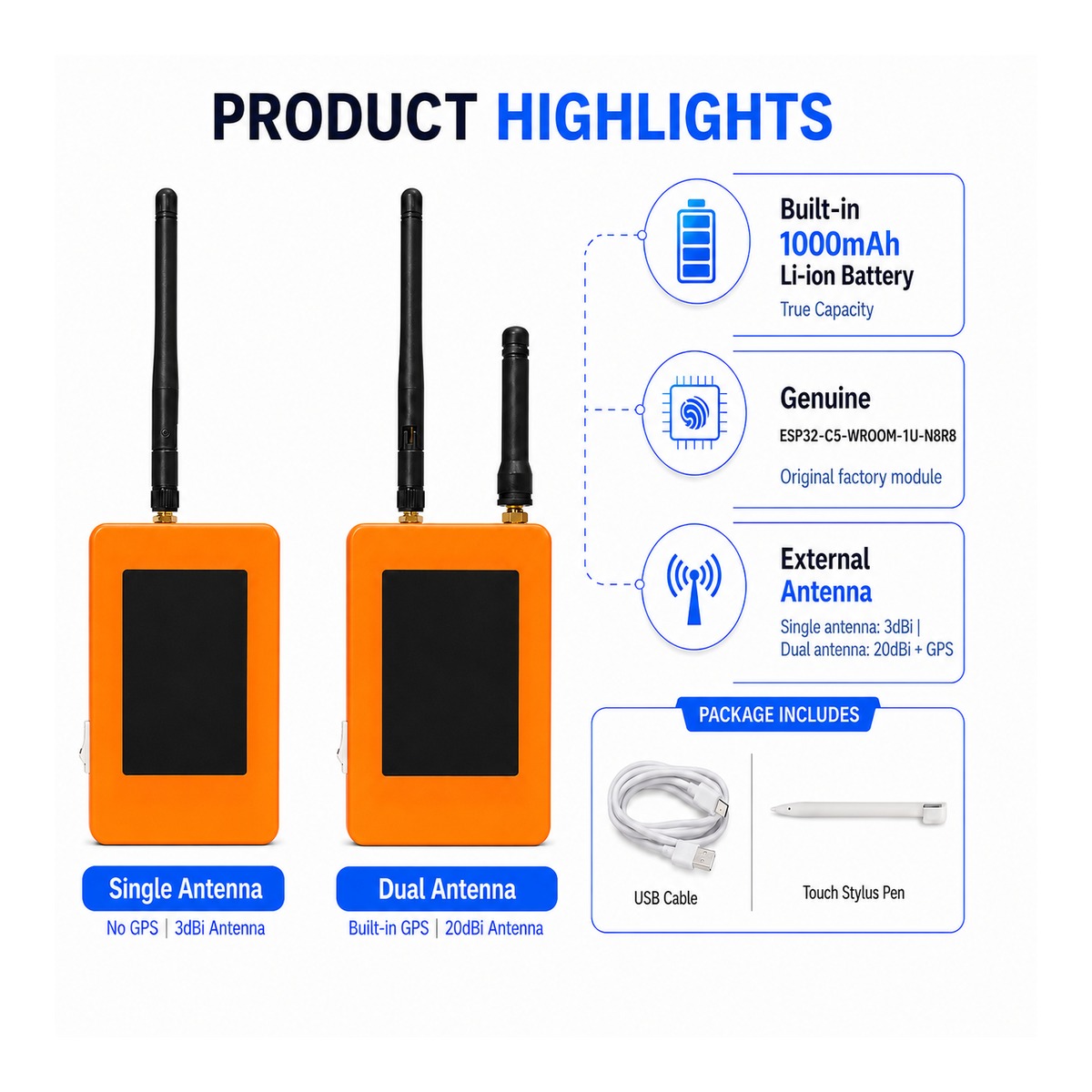
ZLX-ESP32-2
ESP32-C5 2.8 インチ タッチ ディスプレイ開発ボード
1. 製品概要
ZLX-ESP32-2 は、ESP32-C5-WROOM-1U-N8R8 モジュールをベースとした 2.8 インチ抵抗膜タッチ開発ボードです。カラー LCD ディスプレイ、XPT2046 タッチ コントローラー、microSD/TF カード スロット (カード スロットのみ、microSD/TF カードは含まれません)、GPS インターフェイス、オーディオ出力、バッテリー電圧検出、緑色の LED インジケーター、BOOT/RESET ボタン、外部アンテナ インターフェイスが統合されています。 Wi-Fi 6、Bluetooth LE、Zigbee/Thread、ヒューマン マシン インターフェイス (HMI)、データ ログ、およびモノのインターネット (IoT) 開発に適しています。
主な特長
- ESP32-C5 32 ビット RISC-V シングルコア CPU、最大 240 MHz
- ESP32-C5-WROOM-1U-N8R8: 8 MB フラッシュ + 8 MB PSRAM (オンボード モジュール メモリ、microSD/TF カードではありません)
- 2.4 GHz + 5 GHz デュアルバンド Wi-Fi 6 (802.11ax)
- Bluetooth LE、IEEE 802.15.4、Zigbee 3.0、Thread 1.4
- 2.8インチ 240×320 LCDディスプレイ、ST7789ドライバーチップ、BGR初期化、表示反転機能無効
- XPT2046 抵抗膜タッチ コントローラー
- LCD と TF カードは SPI インターフェイスを共有しますが、CS インターフェイスは異なります。タッチ機能は独立したソフトウェア SPI インターフェイスを使用します。
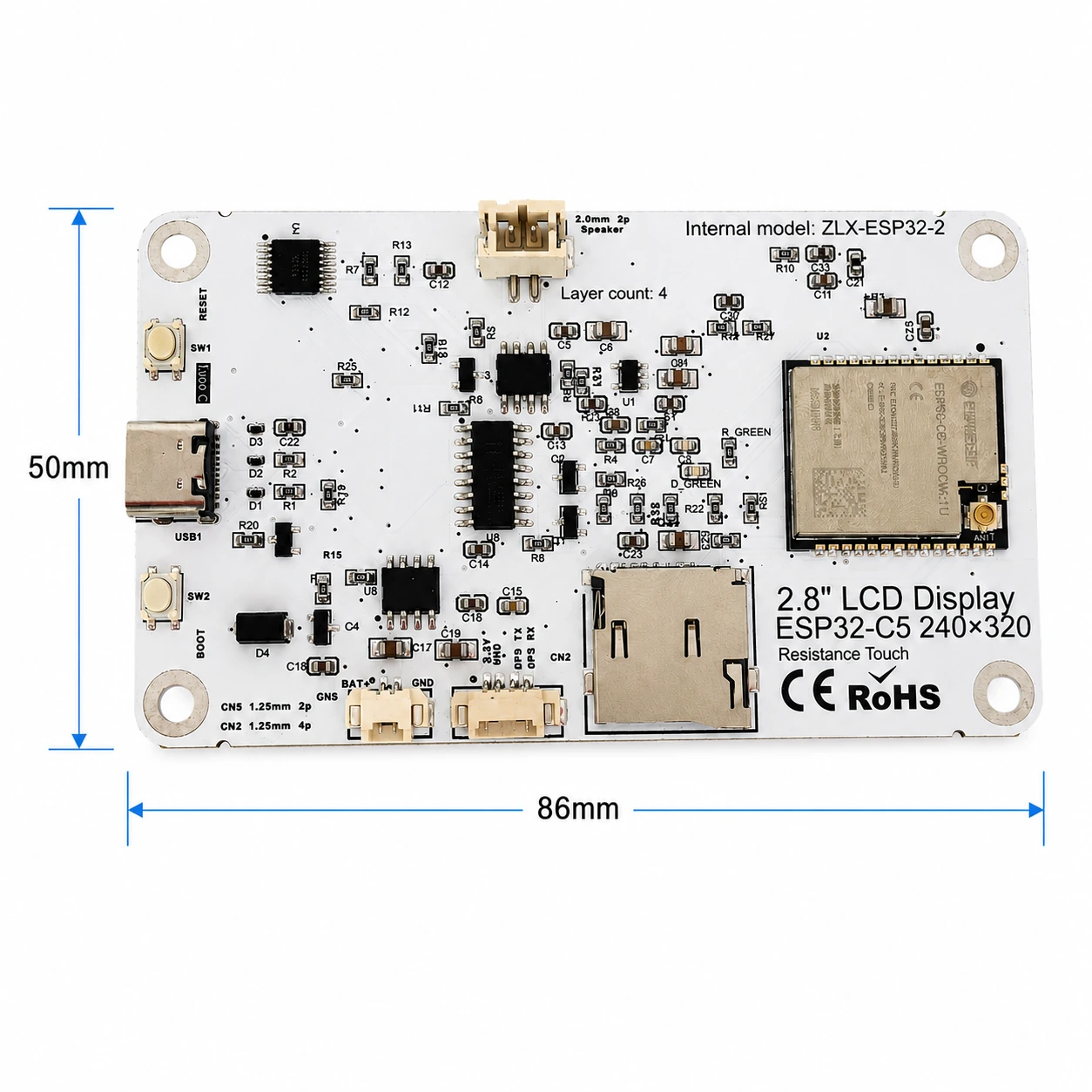
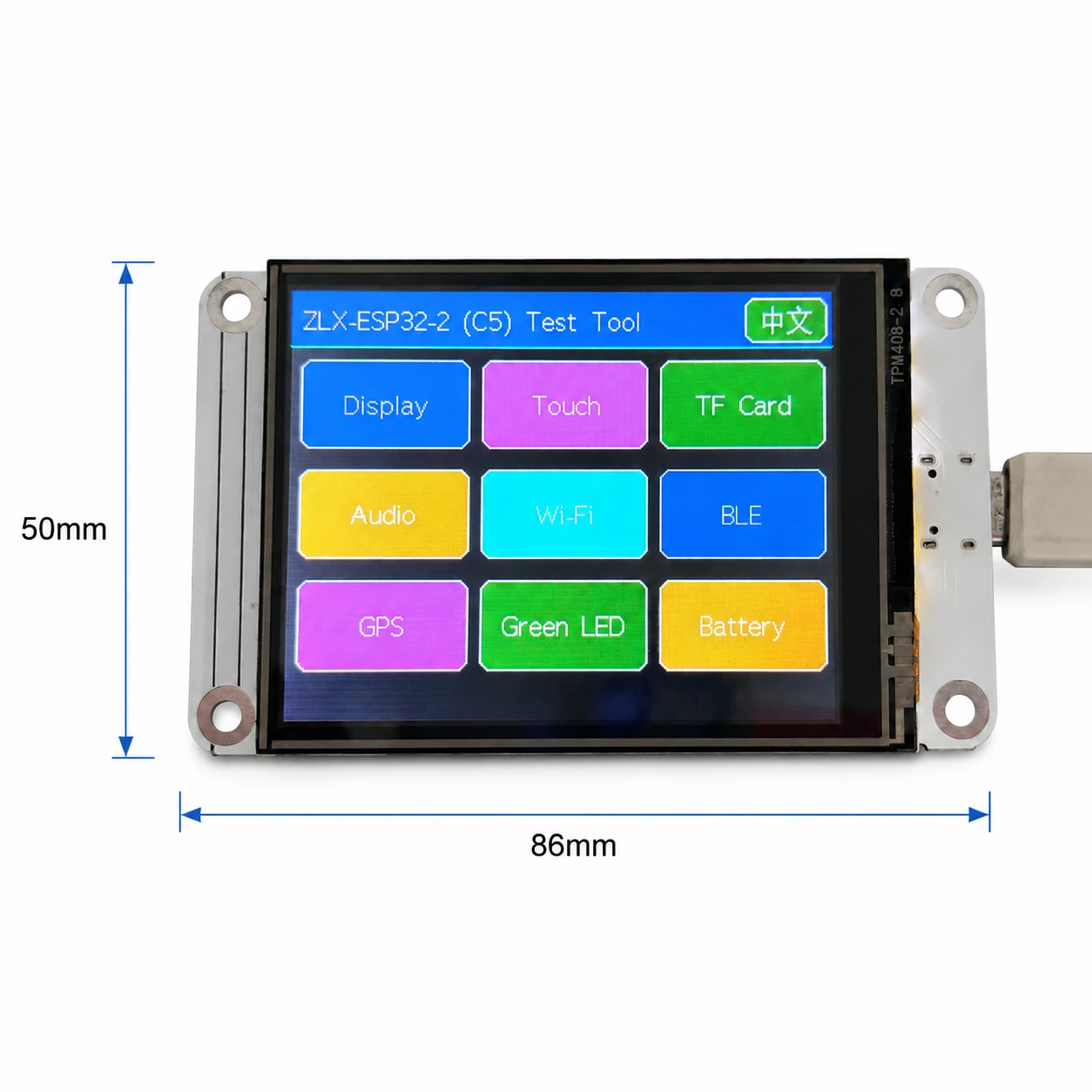
- パネル寸法は約86mm×50mm
- IPEX1 外部アンテナ インターフェイス。ラジオを使用する前に、適切な外部アンテナを接続してください。
対象ユーザー
組み込み開発者、IoT 開発者、メーカー、教育/研究室での使用、製品のプロトタイピングに最適です。
2. 外観とサイズ
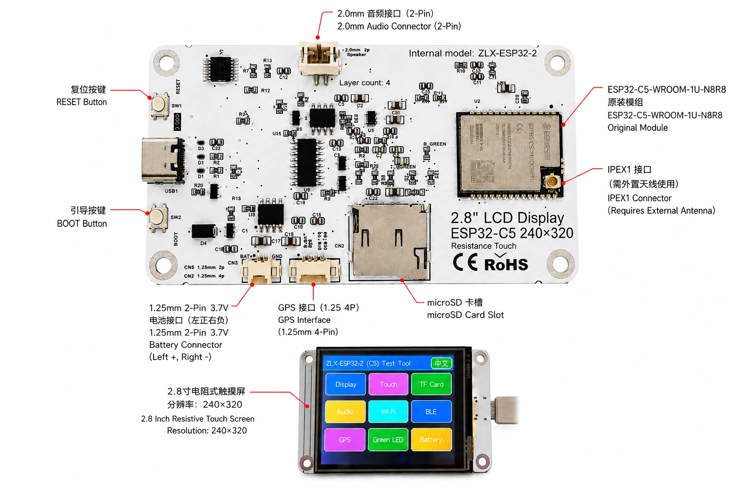
基板寸法は約86mm×50mmです。次の図は、ディスプレイ、コネクタ、主要コンポーネントを識別するのに役立ちます。
コネクタの識別
3. 基板仕様
| もの | 仕様 |
|---|---|
| プレートモデル | ZLX-ESP32-2 |
| コアモジュール | ESP32-C5-WROOM-1U-N8R8 |
| 基板サイズ | 約86×50mm |
| 展示する | 2.8 インチ TFT LCD ディスプレイ、ST7789 チップ、オリジナル解像度 240×320 |
| 色の順序 | BGR の初期化 |
| 反転表示 | オフ/通常表示モード |
| 触る | 抵抗膜タッチ、XPT2046 |
| microSD/TFカードスロット | SPIモード。カードは付属しません |
| GPSインターフェース | 1.25 mm 4ピンコネクタ。 GPIO0/GPIO9 の UART 信号 |
| ボーカル | 2.0mm 2ピンスピーカー/オーディオコネクタ; PWMオーディオ+アンプ有効 |
| バッテリー | 3.7V 単相、1.25mm ダブルピン。保護回路付き、推奨容量1000~3000mAh |
| 外部アンテナ | IPEX1コネクタ。 WROOM-1U 無線パスに必要 |
| ボタン | リセット、スタート |
| 索引 | GPIO26 の緑色の LED |
4. ESP32-C5-WROOM-1U-N8R8モジュール仕様
次の主要なパラメータは、Espressif 公式 ESP32-C5-WROOM-1 / WROOM-1U データ シート v1.2 に基づいています。
| もの | 仕様 |
|---|---|
| 組み込み SoC | ESP32-C5HR8 |
| CPU | 32 ビット RISC-V シングルコア プロセッサ、最大 240 MHz |
| 読み取り専用メモリ | 320 KB |
| HP SRAM | 384 KB |
| LP SRAM | 16 KB |
| フラッシュ | 8MB クアッド SPI |
| PSRAM | 8MB クアッド SPI |
| Wi-Fi | 1T1R、2.4 GHz + 5 GHz デュアルバンド。 IEEE 802.11ax/ac/b/g/n;最大150Mbps |
| 2.4GHzの周波数 | 2412–2484 MHz |
| 5 GHzの周波数 | 5180 ~ 5885 MHz (地域の規制の対象) |
| ブルートゥース | Bluetooth 低エネルギー; Espressif v1.2 の機能リストには Bluetooth Core 6.0 認定が示されています |
| IEEE 802.15.4 | 2.4 GHz OQPSK,250 Kbps |
| Zigbee/Thread | Zigbee 3.0 / Thread 1.4 |
| GPIO | モジュール レベルで最大 22 個の GPIO を使用できます。 |
| Typical Peripherals | GPIO, SPI, UART, I2C, I2S, RMT, LED PWM, USB Serial/JTAG, MCPWM, GDMA, CAN FD, SDIO slave, ADC, temperature sensor, timers, watchdogs, etc. |
| Module Supply | 3.0–3.6 V, typical 3.3 V |
| Recommended Supply Capability | External supply should be capable of at least 0.6 A for the module |
| Ambient Temperature | -40 to +85 °C |
| Module Size | 18.0 × 21.2 × 3.3 mm |
| Antenna | External antenna via connector/module RF path; 50 Ω RF system |
5. Display and Touch
LCD Parameters
| Item | Specification |
|---|---|
| Size | 2.8 inch |
| Driver IC | ST7789 |
| Native resolution | 240 × 320 |
| Landscape logical resolution | 320 × 240 (depending on rotation setting) |
| Color order | BGR |
| Inversion | Disabled / OFF; normal display mode |
| SPI SCK | GPIO6 |
| SPI MOSI | GPIO7 |
| SPI MISO | GPIO2 (shared with TF card; used if required by library/readback) |
| LCD CS | GPIO10 |
| LCD Backlight | GPIO13 |
| LCD DC / RS | GPIO14 |
Touch Parameters
- Touch type: 4-wire resistive; controller: XPT2046.
- DOUT=GPIO3, SCK=GPIO4, DIN=GPIO5.
- CS=GPIO23, IRQ=GPIO25.
- Touch uses an independent software SPI; the supplied test flow is marked as requiring no calibration.
6. GPIO Mapping
The mapping below is based on the supplied GPIO spreadsheet and cross-checked against the schematic. Board peripherals use 19 GPIOs; TX0=GPIO11 and RX0=GPIO12 are additionally used by UART0; GPIO15 is reserved by PSRAM on N8R8, so all 21 usable GPIOs are allocated; EN is not a GPIO.
| GPIO | Signal | Definition | Direction | Function | Notes |
|---|---|---|---|---|---|
| 0 | GPSTX | GPS UART TX | Input | GPS test | GPS module TX → ESP32-C5 |
| 1 | BAT_ADC | Battery voltage sensing | Input/ADC | Battery test | 100k/100k divider; ADC × 2 ≈ battery voltage |
| 2 | SD_MISO | TF DAT0 / LCD MISO shared | Input | TF card test | Shared SPI MISO |
| 3 | RTP_DOUT | XPT2046 DOUT | Input | Touch test | Touch controller data output |
| 4 | RTP_SCK | XPT2046 SCK | Output | Touch test | Independent software SPI |
| 5 | RTP_DIN | XPT2046 DIN | Output | Touch test | Independent software SPI |
| 6 | LCD_SCK | LCD SCK / TF SCK shared | Output | LCD/TF test | Shared SPI clock |
| 7 | LCD_MOSI | LCD MOSI / TF CMD(MOSI) shared | Output | LCD/TF test | Shared SPI MOSI |
| 8 | AUDIOPWM | Audio PWM | Output | Audio test | Audio output control |
| 9 | GPSRX | GPS UART RX | Output | GPS test | ESP32-C5 TX → GPS module RX |
| 10 | LCDCS | ST7789 CS | Output | Display test | LCD chip select |
| 13 | LCDBL | LCD backlight | Output | Display test | Backlight control |
| 14 | LCD_RS/DC | ST7789 DC | Output | Display test | Data/command select |
| 23 | RTPCS | XPT2046 CS | Output | Touch test | Touch chip select |
| 24 | AMP_EN | Amplifier enable | Output | Audio test | High-level enable per supplied mapping; verify actual hardware revision |
| 25 | RTPIRQ | XPT2046 IRQ | Input | Touch test | Touch interrupt |
| 26 | GREENLED | Green LED | Output | LED test | HIGH = ON, LOW = OFF |
| 27 | SDCS | TF DAT3 / CS | Output | TF card test | TF card SPI chip select |
| 28 | BOOTAUTO | BOOT / auto-start control | Input/Control | Factory restore | BOOT input / factory-restore logic |
System and UART Signals
| Signal | Purpose | Note |
|---|---|---|
| RESET_AUTO / EN | ESP32 reset / enable | System enable/reset; not a GPIO |
| UART0_TX / TX0 / GPIO11 | UART0 transmit | Used; excluded from the 19 peripheral GPIO count |
| UART0_RX / RX0 / GPIO12 | UART0 receive | Used; excluded from the 19 peripheral GPIO count |
7. Interface and Bus Sharing
| Item | GPIO | Description |
|---|---|---|
| LCD + TF Shared SPI | GPIO6 / GPIO7 / GPIO2 | SCK, MOSI, MISO shared; devices separated by independent CS |
| LCD CS | GPIO10 | LCD_CS |
| TF card CS | GPIO27 | SD_CS / DAT3 |
| XPT2046 touch | GPIO3 / 4 / 5 / 23 / 25 | DOUT / SCK / DIN / CS / IRQ |
| GPS UART | GPIO0 / GPIO9 | GPSTX / GPSRX; GPIO0 receives GPS TX, GPIO9 drives GPS RX |
| Battery ADC | GPIO1 | BAT_ADC; 100k/100k divider; C20 100 nF filtering |
| Green LED | GPIO26 | HIGH ON, LOW OFF |
| Audio | GPIO8 / GPIO24 | AUDIOPWM / AMP_EN |
| LCD control | GPIO13 / GPIO14 | Backlight / DC |
SPI Sharing Notes
- LCD and TF card share GPIO6 (SCK), GPIO7 (MOSI), and GPIO2 (MISO), but use GPIO10 (LCD_CS) and GPIO27 (SD_CS) respectively.
- Assert only the target device CS at a time to avoid bus contention.
- The XPT2046 touch controller uses an independent software SPI and does not share the main LCD/TF SCK/MOSI signals.
8. Functional Test Mapping
| Test | GPIO | What is tested | Result / Note |
|---|---|---|---|
| Display | GPIO6, 7, 10, 13, 14, 2 | ST7789 display, 240×320 native / 320×240 landscape; BGR; backlight | Normal / Abnormal |
| Touch | GPIO3, 4, 5, 23, 25 | XPT2046 touch response | Test flow: no calibration |
| TF card | GPIO2, 6, 7, 27 | SPI init, read/write/format | Shares SPI with LCD |
| Audio | GPIO8, 24 | PWM audio and amplifier enable | Continuous playback depends on firmware |
| Wi-Fi | Internal RF | 2.4 GHz / 5 GHz scan | No listed GPIO occupied |
| BLE | Internal RF | BLE scan | No listed GPIO occupied |
| GPS | GPIO0, 9 | GPS UART data | GPSTX / GPSRX |
| LED | GPIO26 | Green LED | HIGH on / LOW off |
| Battery | GPIO1 | ADC measures divided battery voltage | Voltage estimate, not a coulomb counter |
| Factory restore | GPIO28 | BOOT input / restore logic | Behavior is defined by firmware |
9. Connector and Electrical Notes
Battery Connector
The board provides a 1.25 mm 2-pin connector for a single-cell 3.7 V battery. In the orientation shown in the labeled image, the left pin is positive (+) and the right pin is negative (-). For battery-powered operation, use a protected single-cell 3.7 V Li-ion/LiPo battery; 1000–3000 mAh is recommended. Verify connector type and polarity before connection. Reverse polarity may damage the board.
Battery Voltage Sensing
GPIO1 senses battery voltage through a 100 kΩ / 100 kΩ divider, so ideally the battery voltage is approximately 2× the ADC pin voltage. This is a voltage estimate only and is not a fuel-gauge/coulomb-counter measurement.
GPS Interface
GPS uses GPIO0 and GPIO9 as UART signals. In this board mapping, GPIO0 (named GPSTX) is an input connected to the GPS module TX, while GPIO9 (named GPSRX) is an output connected to the GPS module RX. For the 1.25 mm 4-pin connector power pins and exact physical pin order, follow the silkscreen/schematic of the specific hardware revision.
External Antenna
ESP32-C5-WROOM-1U is the external-antenna variant. Connect a suitable 2.4/5 GHz, 50-ohm antenna to the IPEX1 connector. Avoid prolonged high-power transmission without a proper antenna attached.
Audio Connector
Audio output uses GPIO8 (AUDIOPWM) for the PWM signal and GPIO24 (AMP_EN) for amplifier enable. The top connector is a 2.0 mm 2-pin audio/speaker connector. Use loads and volume settings within the capability of the actual amplifier circuit.
10. Software Development and Initialization Notes
- Select ST7789 as the display driver and use 240×320 as the native resolution; set rotation for 320×240 landscape as supported by your graphics library.
- Use BGR color order; do not enable display inversion (INVON).
- When LCD and TF share SPI, manage LCD_CS (GPIO10) and SD_CS (GPIO27) independently after initialization.
- XPT2046 は、GPIO3/4/5/23/25 で独立したソフトウェア SPI を使用します。
- バッテリー電圧の場合、精度を向上させるために、約 2:1 の分圧比を使用して GPIO1 ADC 読み取り値を変換し、ADC キャリブレーションを適用します。
- 利用可能な 5 GHz Wi-Fi チャネルと送信電力は、地域の規制によって異なります。
- ブート/工場出荷時リセットの動作はファームウェアによって定義されます。設定がクリアされないように、誤ってアクティブ化しないようにしてください。
推奨される初期化シーケンス
- 電源が安定したら、システムを初期化し、UART をデバッグします。
- LCD SPI を初期化します。 ST7789、BGRを設定し、反転をオフにし、バックライトを有効にします。
- XPT2046タッチを初期化します。
- リムーバブル ストレージが必要な場合は、互換性のあるユーザー提供の microSD/TF カードを挿入し、初期化して LCD_CS/SD_CS ステータスが正しいことを確認します。
- 必要に応じて、GPS、オーディオ、LED、バッテリー ADC を初期化します。
- 必要に応じて、Wi-Fi/BLE/802.15.4 無線機能を有効にします。
11. トラブルシューティング
| 質問 | 解決 |
|---|---|
| 空白/黒い画面を表示する | GPIO6/7/10/13/14、ST7789 ドライバーの選択、BGR 設定、バックライト GPIO13、および反転機能が誤って有効になっているかどうかを確認してください。 |
| 間違った色 | グラフィックス ライブラリが BGR カラー オーダーに設定されていることを確認します。 |
| タッチ反応なし | GPIO3/4/5/23/25 および XPT2046 の初期化を確認します。 |
| TFカードの初期化に失敗しました | 共有 SPI SCK/MOSI/MISO を確認し、SD_CS (GPIO27) と LCD_CS (GPIO10) が同時に設定されていないことを確認します。 |
| Wi-Fi信号が弱い/Wi-Fiがありません | IPEX1 外部アンテナが接続されており、2.4/5 GHz 帯域に適していることを確認します。 |
| 電池残量が半分くらい | GPIO1 は 100k/100k 分圧器を使用します。 ADC 側の電圧を約 2 倍します。 |
| GPSデータがありません | GPIO0 が GPS TX を受信し、GPIO9 が GPS RX を駆動することを確認し、ボー レートと電力を確認します。 |
12. ダウンロードと技術サポート
ZLX-ESP32-2 ファームウェア、ファイル、フォローアップ ドキュメント、および関連サポートについては、ZLX ESP32 開発ボード サポート センターをご覧ください。ファームウェアをフラッシュする前に、Web サイトに表示されている PCB モデルがハードウェアと正確に一致していることを必ず確認してください。
ダウンロードリンク:https://www.zlxchina.xyz/
Espressif モジュール データ シート: ESP32-C5-WROOM-1 / WROOM-1U データ シート
参照
13. 安全性と操作性
- 接続する前にバッテリーの極性を確認してください。バッテリーコネクタを逆に接続しないでください。
- IPEX コネクタを抜き差しするときは、RF ソケットの損傷を避けるために、垂直方向の力を加え、横方向のこじ開けを避けてください。
- 露出した回路基板を使用する場合は、静電気放電に対する保護措置を講じ、金属物によるショートを防止してください。
- 5 GHz の無線帯域、チャネル、送信電力は、地域の規制に準拠する必要があります。
- TF カード、GPS、オーディオ、その他の周辺機器については、実際のハードウェア バージョンで指定されている電源とロジック レベルに従ってください。明示的に検証しない限り、3.3V を超えるロジック レベルを I/O ピンに印加しないでください。
14. 文書の改訂履歴
| 祭司 | 日付 | 説明する | ベース |
|---|---|---|---|
| V1.1 | 2026-08-25 | microSD/TF カード、バッテリー、GPIO の手順を改訂しました。 | 合肥志楽興情報技術有限公司 |
-終わり-