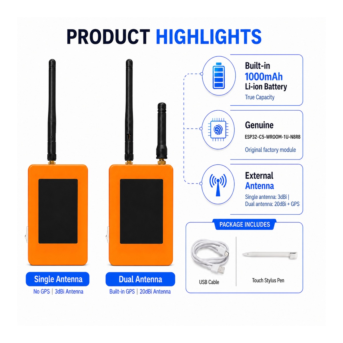
ZLX-ESP32-2
ESP32-C5 2,8 "Touch Display Development Board
1. Productoverzicht
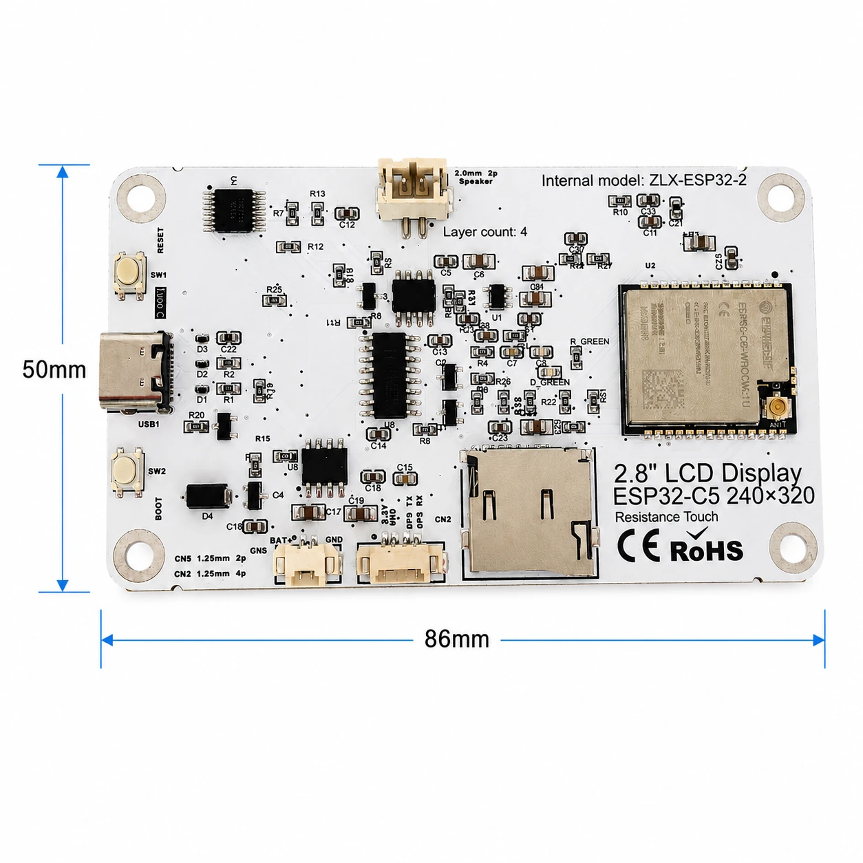
De ZLX-ESP32-2 is een 2,8-inch resistief touch-ontwikkelbord op basis van de ESP32-C5-WROOM-1U-N8R8-module. Het integreert een kleuren LCD-scherm, XPT2046 aanraakcontroller, microSD/TF-kaartsleuf (alleen kaartsleuf, exclusief microSD/TF-kaart), GPS-interface, audio-uitgang, accuspanningsdetectie, groene LED-indicator, opstart-/resetknop en externe antenne-interface. Het is geschikt voor Wi-Fi 6, Bluetooth LE, Zigbee/Thread, Human Machine Interface (HMI), Data Logging en Internet of Things (IoT) ontwikkeling.
Belangrijkste kenmerken
- ESP32-C5 32-bits RISC-V Single Core CPU @ 240 MHz
- ESP32-C5-WROOM-1U-N8R8: 8 MB Flash + 8 MB PSRAM (ingebouwd modulegeheugen, niet-microSD/TF-kaart)
- 2,4 GHz + 5 GHz dual-band Wi-Fi 6 (802.11ax)
- Bluetooth LE、IEEE 802.15.4、Zigbee 3.0、Thread 1.4
- 2,8 inch 240 × 320 LCD display, ST7789 driver chip, BGR initialisatie, display inversie functie is uitgeschakeld
- XPT2046 Resistieve aanraakcontroller
- De LCD- en TF-kaart delen één SPI-interface, maar de CS-interface is anders; de aanraakfunctie maakt gebruik van een aparte software SPI-interface.
- Formaat vel circa 86 mm x 50 mm
- IPEX1 externe antenne-interface; sluit de juiste externe antenne aan voordat u de radio gebruikt.
Producten
Voor embedded ontwikkelaars, IoT-ontwikkelaars, makers, educatief/lab-gebruik en productprototyping.
2. Uiterlijk en afmetingen
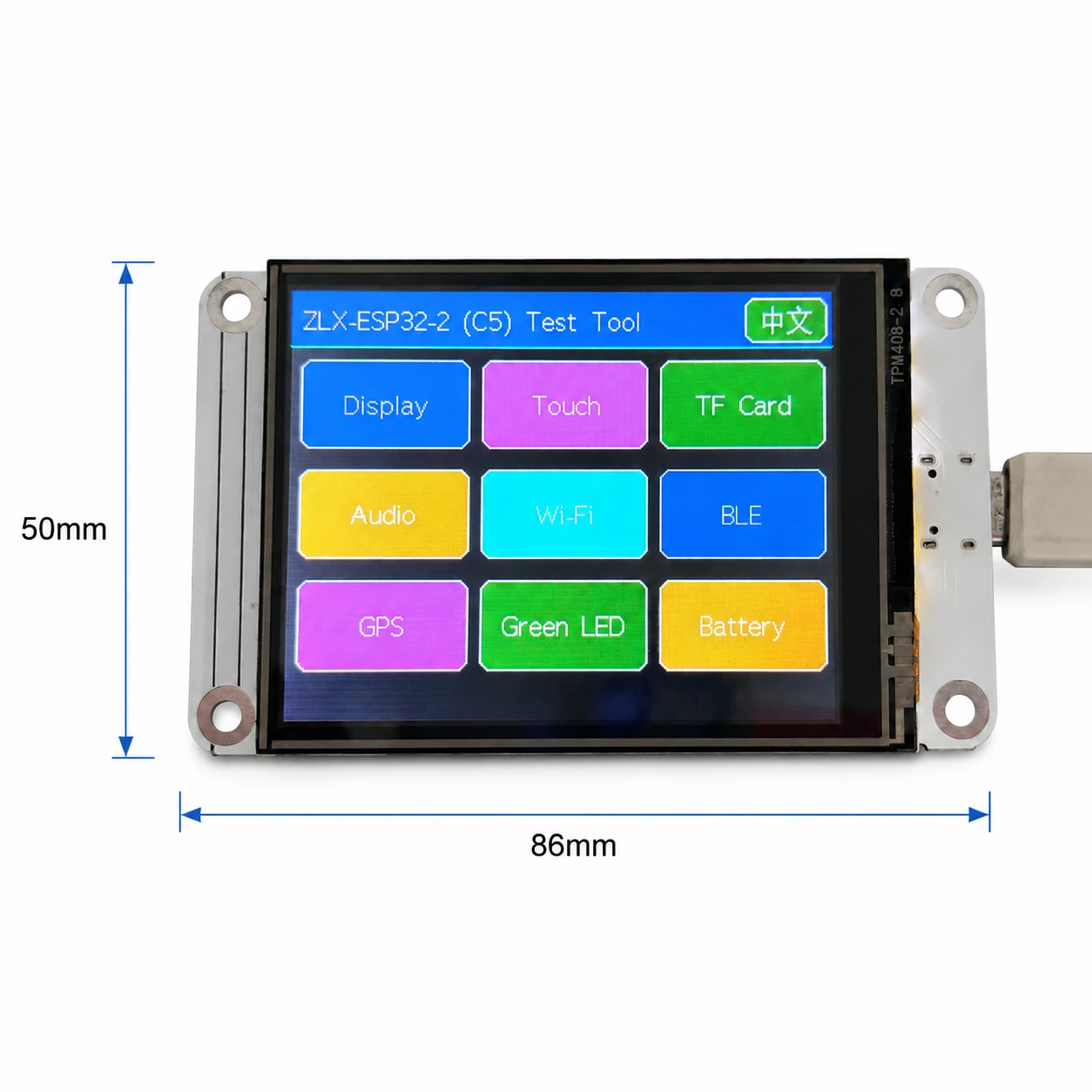
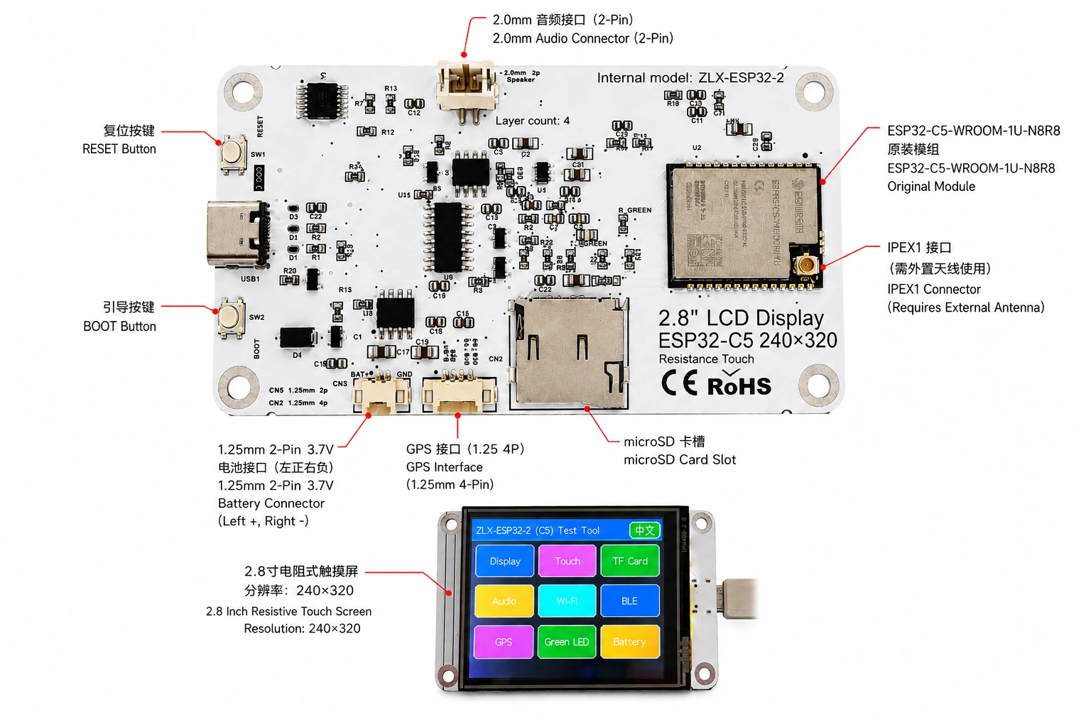
De afmeting van de plank is ongeveer 86 mm x 50 mm. De onderstaande afbeelding helpt bij het identificeren van het display, de connectoren en de belangrijkste componenten.
Connectoridentificatie
3. Specificaties printplaat
| Item | Specificaties |
|---|---|
| Plaatmodel | ZLX-ESP32-2 |
| Kernmodules | ESP32-C5-WROOM-1U-N8R8 |
| Plaatgrootte | Ca. 86 x 50 mm |
| Oriëntatie | 2.8 "TFT LCD, ST7789 chip, originele resolutie 240 × 320 |
| Kleurvolgorde | BGR Initialisatie |
| Omgekeerd tonen | Uit/Normale weergavemodus |
| Aanraking | Weerstand biedende aanraking XPT2046 |
| microSD/TF-kaartsleuf | SPI-modus; kaart niet inbegrepen |
| GPS-interface | 1,25 mm 4-pins connector; UART-signaal op GPIO0/GPIO9 |
| akoestisch | 2,0 mm 2-pins luidspreker/audioconnector; PWM-audio + versterker ingeschakeld |
| Ijsbatterij | 3,7 V enkelfasig, 1,25 mm dubbelpolig; met beveiligingscircuit, aanbevolen capaciteit 1000-3000 mAh |
| Externe antenne | IPEX1-connector; vereist voor WROOM-1U draadloos pad |
| Knoppen | Resetten, opstarten |
| Statistieken | Groene LED op GPIO26 |
4. Specificaties ESP32-C5-WROOM-1U-N8R8-module
De volgende belangrijke parameters zijn gebaseerd op Espressif official ESP32-C5-WROOM-1/WROOM-1U datasheet v1.2.
| Item | Specificaties |
|---|---|
| Ingebedde SoC's | ESP32-C5HR8 |
| CPU | 32-bit RISC-V single-core processor tot 240 MHz |
| alleen-lezen geheugen | 320 KB |
| HP SRAM | 384 KB |
| LP SRAM | 16 KB |
| flash | 8 MB Quad Channel SPI |
| PSRAM | 8 MB Quad Channel SPI |
| Wifi | 1T1R, 2,4 GHz + 5 GHz dual band; IEEE 802.11ax/ac/b/g/n; tot 150 Mbps |
| 2,4 GHz-frequentie | 2412–2484 MHz |
| 5 GHz frequentie | 5180–5885 MHz (onderhevig aan lokale regelgeving) |
| Bluetooth | Bluetooth Low Energy; Espressif v1.2 functielijst toont gecertificeerde Bluetooth Core 6.0 |
| IEEE 802.15.4 | 2.4 GHz OQPSK,250 Kbps |
| Zigbee/Thread | Zigbee 3.0 / Thread 1.4 |
| GPIO | Er zijn maximaal 22 GPIO's beschikbaar op moduleniveau. |
| Typical Peripherals | GPIO, SPI, UART, I2C, I2S, RMT, LED PWM, USB Serial/JTAG, MCPWM, GDMA, CAN FD, SDIO slave, ADC, temperature sensor, timers, watchdogs, etc. |
| Module Supply | 3.0–3.6 V, typical 3.3 V |
| Recommended Supply Capability | External supply should be capable of at least 0.6 A for the module |
| Ambient Temperature | -40 to +85 °C |
| Module Size | 18.0 × 21.2 × 3.3 mm |
| Antenna | External antenna via connector/module RF path; 50 Ω RF system |
5. Display and Touch
LCD Parameters
| Item | Specification |
|---|---|
| Size | 2.8 inch |
| Driver IC | ST7789 |
| Native resolution | 240 × 320 |
| Landscape logical resolution | 320 × 240 (depending on rotation setting) |
| Color order | BGR |
| Inversion | Disabled / OFF; normal display mode |
| SPI SCK | GPIO6 |
| SPI MOSI | GPIO7 |
| SPI MISO | GPIO2 (shared with TF card; used if required by library/readback) |
| LCD CS | GPIO10 |
| LCD Backlight | GPIO13 |
| LCD DC / RS | GPIO14 |
Touch Parameters
- Touch type: 4-wire resistive; controller: XPT2046.
- DOUT=GPIO3, SCK=GPIO4, DIN=GPIO5.
- CS=GPIO23, IRQ=GPIO25.
- Touch uses an independent software SPI; the supplied test flow is marked as requiring no calibration.
6. GPIO Mapping
The mapping below is based on the supplied GPIO spreadsheet and cross-checked against the schematic. Board peripherals use 19 GPIOs; TX0=GPIO11 and RX0=GPIO12 are additionally used by UART0; GPIO15 is reserved by PSRAM on N8R8, so all 21 usable GPIOs are allocated; EN is not a GPIO.
| GPIO | Signal | Definition | Direction | Function | Notes |
|---|---|---|---|---|---|
| 0 | GPSTX | GPS UART TX | Input | GPS test | GPS module TX → ESP32-C5 |
| 1 | BAT_ADC | Battery voltage sensing | Input/ADC | Battery test | 100k/100k divider; ADC × 2 ≈ battery voltage |
| 2 | SD_MISO | TF DAT0 / LCD MISO shared | Input | TF card test | Shared SPI MISO |
| 3 | RTP_DOUT | XPT2046 DOUT | Input | Touch test | Touch controller data output |
| 4 | RTP_SCK | XPT2046 SCK | Output | Touch test | Independent software SPI |
| 5 | RTP_DIN | XPT2046 DIN | Output | Touch test | Independent software SPI |
| 6 | LCD_SCK | LCD SCK / TF SCK shared | Output | LCD/TF test | Shared SPI clock |
| 7 | LCD_MOSI | LCD MOSI / TF CMD(MOSI) shared | Output | LCD/TF test | Shared SPI MOSI |
| 8 | AUDIOPWM | Audio PWM | Output | Audio test | Audio output control |
| 9 | GPSRX | GPS UART RX | Output | GPS test | ESP32-C5 TX → GPS module RX |
| 10 | LCDCS | ST7789 CS | Output | Display test | LCD chip select |
| 13 | LCDBL | LCD backlight | Output | Display test | Backlight control |
| 14 | LCD_RS/DC | ST7789 DC | Output | Display test | Data/command select |
| 23 | RTPCS | XPT2046 CS | Output | Touch test | Touch chip select |
| 24 | AMP_EN | Amplifier enable | Output | Audio test | High-level enable per supplied mapping; verify actual hardware revision |
| 25 | RTPIRQ | XPT2046 IRQ | Input | Touch test | Touch interrupt |
| 26 | GREENLED | Green LED | Output | LED test | HIGH = ON, LOW = OFF |
| 27 | SDCS | TF DAT3 / CS | Output | TF card test | TF card SPI chip select |
| 28 | BOOTAUTO | BOOT / auto-start control | Input/Control | Factory restore | BOOT input / factory-restore logic |
System and UART Signals
| Signal | Purpose | Note |
|---|---|---|
| RESET_AUTO / EN | ESP32 reset / enable | System enable/reset; not a GPIO |
| UART0_TX / TX0 / GPIO11 | UART0 transmit | Used; excluded from the 19 peripheral GPIO count |
| UART0_RX / RX0 / GPIO12 | UART0 receive | Used; excluded from the 19 peripheral GPIO count |
7. Interface and Bus Sharing
| Item | GPIO | Description |
|---|---|---|
| LCD + TF Shared SPI | GPIO6 / GPIO7 / GPIO2 | SCK, MOSI, MISO shared; devices separated by independent CS |
| LCD CS | GPIO10 | LCD_CS |
| TF card CS | GPIO27 | SD_CS / DAT3 |
| XPT2046 touch | GPIO3 / 4 / 5 / 23 / 25 | DOUT / SCK / DIN / CS / IRQ |
| GPS UART | GPIO0 / GPIO9 | GPSTX / GPSRX; GPIO0 receives GPS TX, GPIO9 drives GPS RX |
| Battery ADC | GPIO1 | BAT_ADC; 100k/100k divider; C20 100 nF filtering |
| Green LED | GPIO26 | HIGH ON, LOW OFF |
| Audio | GPIO8 / GPIO24 | AUDIOPWM / AMP_EN |
| LCD control | GPIO13 / GPIO14 | Backlight / DC |
SPI Sharing Notes
- LCD and TF card share GPIO6 (SCK), GPIO7 (MOSI), and GPIO2 (MISO), but use GPIO10 (LCD_CS) and GPIO27 (SD_CS) respectively.
- Assert only the target device CS at a time to avoid bus contention.
- The XPT2046 touch controller uses an independent software SPI and does not share the main LCD/TF SCK/MOSI signals.
8. Functional Test Mapping
| Test | GPIO | What is tested | Result / Note |
|---|---|---|---|
| Display | GPIO6, 7, 10, 13, 14, 2 | ST7789 display, 240×320 native / 320×240 landscape; BGR; backlight | Normal / Abnormal |
| Touch | GPIO3, 4, 5, 23, 25 | XPT2046 touch response | Test flow: no calibration |
| TF card | GPIO2, 6, 7, 27 | SPI init, read/write/format | Shares SPI with LCD |
| Audio | GPIO8, 24 | PWM audio and amplifier enable | Continuous playback depends on firmware |
| Wi-Fi | Internal RF | 2.4 GHz / 5 GHz scan | No listed GPIO occupied |
| BLE | Internal RF | BLE scan | No listed GPIO occupied |
| GPS | GPIO0, 9 | GPS UART data | GPSTX / GPSRX |
| LED | GPIO26 | Green LED | HIGH on / LOW off |
| Battery | GPIO1 | ADC measures divided battery voltage | Voltage estimate, not a coulomb counter |
| Factory restore | GPIO28 | BOOT input / restore logic | Behavior is defined by firmware |
9. Connector and Electrical Notes
Battery Connector
The board provides a 1.25 mm 2-pin connector for a single-cell 3.7 V battery. In the orientation shown in the labeled image, the left pin is positive (+) and the right pin is negative (-). For battery-powered operation, use a protected single-cell 3.7 V Li-ion/LiPo battery; 1000–3000 mAh is recommended. Verify connector type and polarity before connection. Reverse polarity may damage the board.
Battery Voltage Sensing
GPIO1 senses battery voltage through a 100 kΩ / 100 kΩ divider, so ideally the battery voltage is approximately 2× the ADC pin voltage. This is a voltage estimate only and is not a fuel-gauge/coulomb-counter measurement.
GPS Interface
GPS uses GPIO0 and GPIO9 as UART signals. In this board mapping, GPIO0 (named GPSTX) is an input connected to the GPS module TX, while GPIO9 (named GPSRX) is an output connected to the GPS module RX. For the 1.25 mm 4-pin connector power pins and exact physical pin order, follow the silkscreen/schematic of the specific hardware revision.
External Antenna
ESP32-C5-WROOM-1U is the external-antenna variant. Connect a suitable 2.4/5 GHz, 50-ohm antenna to the IPEX1 connector. Avoid prolonged high-power transmission without a proper antenna attached.
Audio Connector
Audio output uses GPIO8 (AUDIOPWM) for the PWM signal and GPIO24 (AMP_EN) for amplifier enable. The top connector is a 2.0 mm 2-pin audio/speaker connector. Use loads and volume settings within the capability of the actual amplifier circuit.
10. Software Development and Initialization Notes
- Select ST7789 as the display driver and use 240×320 as the native resolution; set rotation for 320×240 landscape as supported by your graphics library.
- Use BGR color order; do not enable display inversion (INVON).
- When LCD and TF share SPI, manage LCD_CS (GPIO10) and SD_CS (GPIO27) independently after initialization.
- XPT2046 maakt gebruik van standalone software SPI op GPIO3/4/5/23/25.
- Voor accuspanning, converteer GPIO1 ADC-metingen met behulp van een gedeeltelijke spanningsverhouding van ongeveer 2: 1 en pas ADC-kalibratie toe voor een hogere nauwkeurigheid.
- Beschikbare 5 GHz Wi-Fi-kanalen en zendvermogen zijn afhankelijk van lokale regelgeving.
- Het gedrag van het starten/herstellen van fabrieksinstellingen wordt bepaald door de firmware; vermijd onbedoelde activering om te voorkomen dat de instellingen worden gewist.
Voorgestelde initialisatievolgorde
- Wanneer de stroom stabiel is, initialiseert u het systeem en debugt u de UART.
- Initialiseer LCD SPI; configureer ST7789, BGR, schakel inversie uit en schakel achtergrondverlichting in.
- Initialiseer XPT2046-touch.
- Als verwijderbare opslag vereist is, plaatst u een compatibele door de gebruiker geleverde microSD/TF-kaart, initialiseert u deze en zorgt u ervoor dat de LCD_CS/SD_CS-status correct is.
- Initialiseer indien nodig GPS-, audio-, LED- en batterij-ADC's.
- Schakel indien nodig Wi-Fi/BLE/802.15.4-radio in.
11. Problemen oplossen
| probleem | Oplossingen |
|---|---|
| Toon leeg/zwart scherm | Controleer GPIO6/7/10/13/14, ST7789 aandrijfselectie, BGR-instellingen, GPIO13 met achtergrondverlichting en of inversie per ongeluk is ingeschakeld. |
| Kleurfout | Controleer of de grafische bibliotheek is geconfigureerd voor BGR-kleurvolgorde. |
| Geen aanraakreactie | Controleer initialisatie van GPIO3/4/5/23/25 en XPT2046. |
| Initialisatie TF-kaart mislukt | Controleer de gedeelde SPI SCK/MOSI/miso en zorg ervoor dat SD_CS (GPIO27) en LCD_CS (GPIO10) niet tegelijkertijd zijn ingesteld. |
| Wi-Fi-signaal zwak/geen wifi | Controleer of de IPEX1 externe antenne is aangesloten en werkt in de 2.4/5 GHz-band. |
| Ongeveer de helft van de batterijmetingen | GPIO1 gebruikt een 100k/100k spanningsdeler; vermenigvuldig de ADC-zijspanning met ongeveer 2. |
| Geen GPS-gegevens | Controleer of GPIO0 GPS TX ontvangt, GPIO9 GPS RX aanstuurt en de baudrate en voeding verifieert. |
12. Downloads en technische ondersteuning
Ga voor ZLX-ESP32-2-firmware, documentatie, vervolgdocumentatie en gerelateerde ondersteuning naar het ZLX ESP32 Development Board Support Center. Voordat u de firmware knippert, moet u ervoor zorgen dat het PCB-model op de website precies overeenkomt met uw hardware.
Downloadlink:https://www.zlxchina.xyz/
Lexin Module Datablad: ESP32-C5-WROOM-1/WROOM-1U Datablad
Referentie
- ZLX ESP32 Development Board Support Center
- Espressif ESP32-C5-WROOM-1 & WROOM-1U Datablad v1.2 (2026-08-12)
13. Veiligheid en bediening
- Controleer de polariteit van de batterij voordat u deze aansluit; keer de batterijconnector nooit om.
- Oefen bij het aansluiten en loskoppelen van de IPEX-connector verticaal kracht uit en vermijd lateraal wrikken om beschadiging van de RF-aansluiting te voorkomen.
- Neem bij het gebruik van blote printplaten beveiligingsmaatregelen tegen elektrostatische ontlading en voorkom kortsluiting veroorzaakt door metalen voorwerpen.
- 5 GHz radiobanden, kanalen en zendvermogen moeten voldoen aan de lokale voorschriften.
- Volg voor TF-kaarten, GPS, audio en andere randapparatuur de vermogens- en logische niveaus die zijn gespecificeerd in de werkelijke hardwareversie. Pas geen logisch niveau hoger dan 3,3 V toe op I/O-pinnen, tenzij expliciet geverifieerd.
14. Revisiegeschiedenis van documenten
| Priester | Datum | Beschrijving | Bovenliggend |
|---|---|---|---|
| V1.1 | 2026-08-25 | Herziene instructies voor microSD/TF-kaarten, batterijen en GPIO. | Hefei Zhiluxing Information Technology Co., Ltd. |
SLOT